Wireless stress tester of hydro-power generating unit

A technology of hydroelectric unit and tester, which is applied in the direction of applying repeated force/pulsation force to test the strength of materials, instruments, and measuring force, which can solve the problems of strong danger, inconvenient wiring, and low work efficiency, and reduce the difficulty of operation , Simplify maintenance work, improve test efficiency

Active Publication Date: 2011-02-09
STATE GRID HUBEI ELECTRIC POWER RES INST
View PDF4 Cites 8 Cited by
  • Summary
  • Abstract
  • Description
  • Claims
  • Application Information

AI Technical Summary

Problems solved by technology

[0004] 1. The signal transmission in the stress test is generally wired transmission. Due to the inconvenient wiring and high risk, the stress measurement of many components of the hydroelectric unit cannot be realized;
[0005] 2. Most of the stress testing devices are bulky, and the analysis methods are simple or low in precision;
[0006] 3. It is generally used for the measurement of fixed parts of hydroelectric units. There is no good method for stress measurement of rotating parts, especially the runner and main shaft of key parts of hydro turbines.
Due to the rotation of these parts, offline recording devices can only be used for post-event data analysis. However, due to the complexity of unit operating conditions and the non-arbitrary nature of unit scheduling, the work efficiency of the test is very low, and even more than ten days of work All in vain occurs, which is a considerable loss of manpower and material resources in some key projects
[0007] 4. Ordinary wireless transmission can only be used to transmit non-real-time measurement results due to high bit error rate and lack of technical means such as network protocol layer control, which is incompetent for complex multi-channel analysis

Method used


Image

  • Wireless stress tester of hydro-power generating unit
  • Wireless stress tester of hydro-power generating unit
  • Wireless stress tester of hydro-power generating unit

Examples


Embodiment Construction

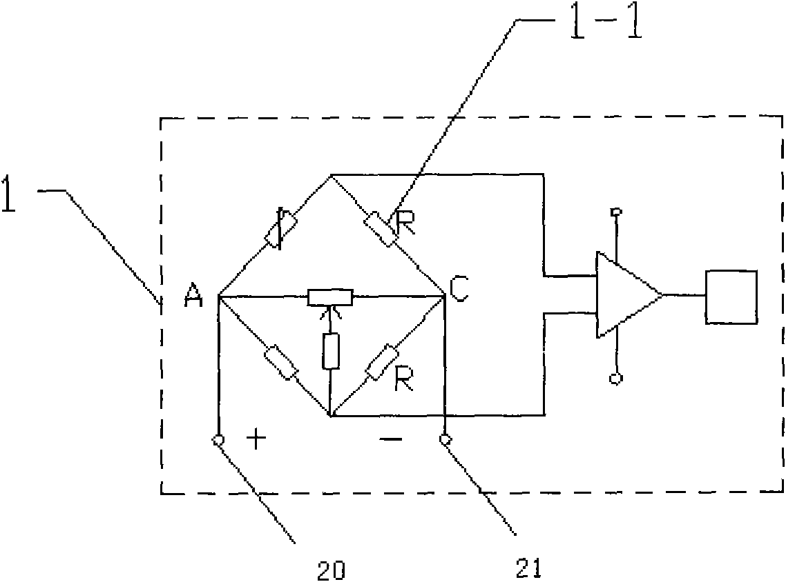
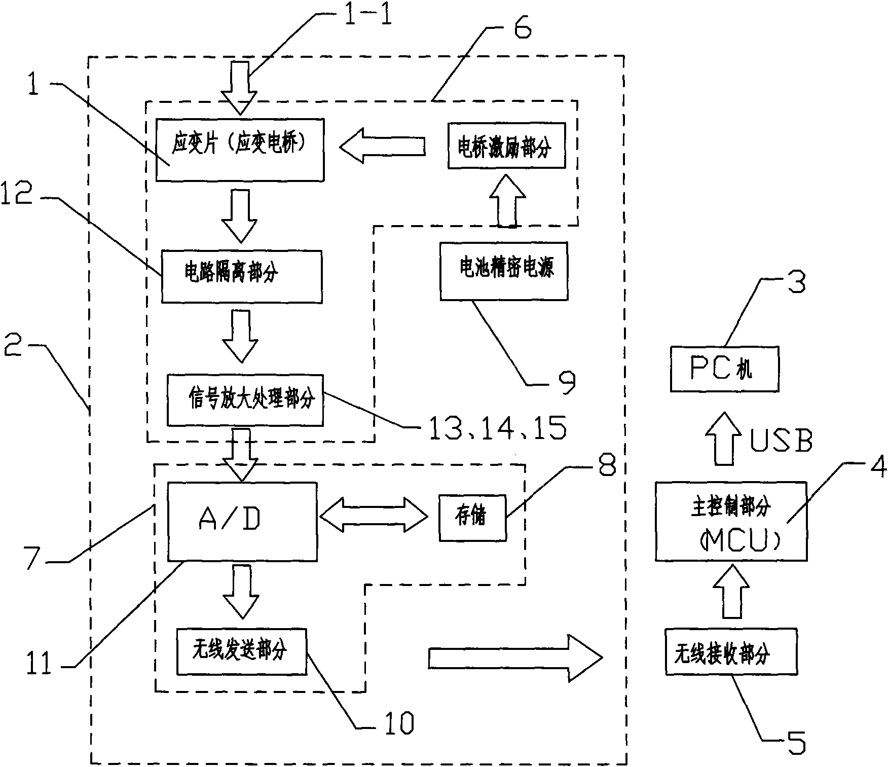
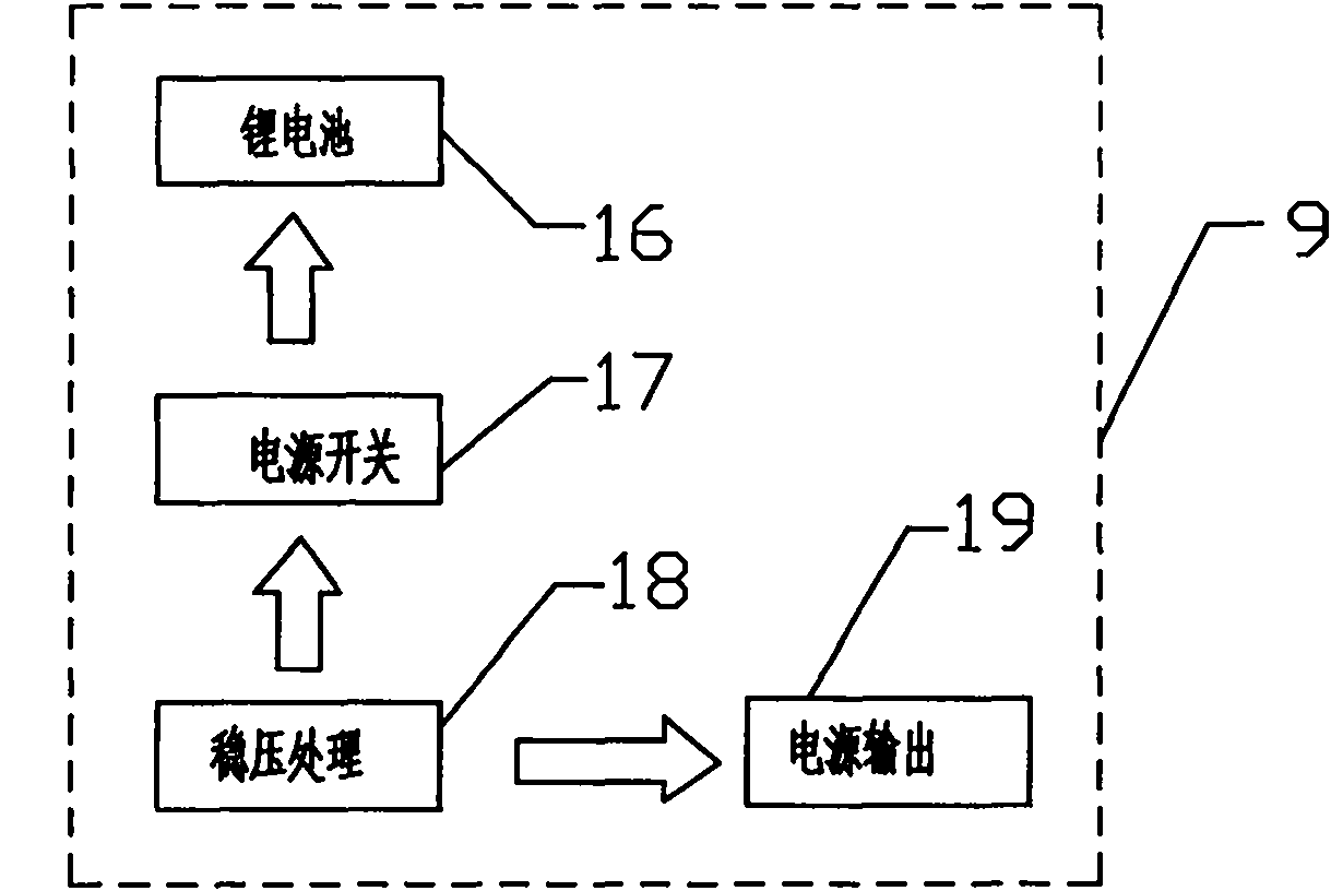
[0031] Below in conjunction with accompanying drawing, the present invention will be further described, figure 2 Among them, the wireless stress tester for hydropower units at least includes a lower distributed acquisition system 2 for signal acquisition, processing and storage and an upper and lower wireless signal transmitter 10, 5 for signal transmission; the lower distributed The acquisition system 2 includes a signal conditioner 6 for voltage and current conversion, filtering, overcoming signal drift, photoelectric isolation, electrostatic shielding and multi-stage amplification, an A / D conversion, storage, and and a lower master controller 7 for wireless transmission and a precision power supply 9 , the lower master controller 7 is composed of an A / D conversion and signal processor 11 , a data memory 8 and a lower wireless signal transmitter 10 . figure 1 with Image 6Among them, the signal conditioner 6 is provided with a strain bridge 1 for removing noise, amplifying...


PUM


Abstract

The invention discloses a wireless stress tester of a hydro-power generating unit. The wireless stress tester at least comprises a lower distributed acquisition system (2) for signal acquisition, processing and storage and upper and lower wireless signal transmitters (10, 5) for signal transmission; the lower distributed acquisition system (2) comprises a signal conditioner (6), a lower main controller (7) and a precision power supply (9), wherein the signal conditioner (6) is used for voltage and current conversion, photoelectric isolation, electrostatic shielding and multistage amplification, and the lower main controller (7) is used for processing the output signals of the signal conditioner (6) and used for A/D conversion, data storage and wireless signal transmission; and the lower distributed acquisition system is in wireless data communication connection with a receiver of the upper wireless signal transmitter (5) in an upper main controller (4) through a transmitter of the lower wireless signal transmitter (10). The wireless stress tester has the advantages of high precision, acquired number accuracy, high time efficiency, reasonability and accuracy of the acquired test data, improvement on the success rate of test, and capability of ensuring the fairness of the test result.

Description

technical field [0001] The invention relates to testing equipment for hydroelectric generators, in particular to a wireless stress tester for hydroelectric generators. Background technique [0002] The water turbine is an important energy conversion power device in a hydroelectric unit, and the shaft and main shaft of the water turbine are important underwater and water rotating components. Due to the effect of the hydraulically unstable flow field and the complex geometry of the runner blades, the loads on the turbines are very complex. In addition to the centrifugal force and pressure loads generated by the water flow, the turbine blades are also subject to pressure pulsation and various instabilities inside the draft tube. Hydraulic dynamic load, and the combined effect of dynamic load caused by various mechanical and electromagnetic forces. Therefore, the blade is easy to generate complex dynamic stress, causing fatigue damage such as blade vibration and cracks. When a...

Claims


Application Information

Patent Timeline
Patent Type & Authority Applications(China)
IPC IPC(8): G08C17/02G01L1/00G01N3/32
CPCY02B60/50
Inventor 翟建平梁涛
Owner STATE GRID HUBEI ELECTRIC POWER RES INST
Why Eureka
Try Eureka