Self-powered automatic switching and closing high-voltage control system

An automatic switching and high-voltage control technology, which is applied in the direction of electrical components, circuit devices, emergency power supply arrangements, etc., can solve the problem of inability to guarantee the long-term normal operation of vacuum circuit breakers and relay protection, unreasonable high-voltage control systems, and violation of power supply policy requirements, etc. Problems, achieve the effect of shortening the production cycle, easy procurement, and ensuring reliability

Active Publication Date: 2011-02-09
HUNAN YANNENG SENYUAN ELECTRIC POWER EQUIP
View PDF4 Cites 9 Cited by
  • Summary
  • Abstract
  • Description
  • Claims
  • Application Information

AI Technical Summary

Problems solved by technology

[0004] However, nowadays, more and more units adopt two main and backup 10kV high-voltage power supplies to enter the household, especially those who use electricity as a first-level load unit. Because of the unreasonable original high-voltage control system, it brings a lot of inconvenience to users and violates the The power supply policy requirements of "uninterrupted, high-quality, economical and safe"
At present, the operating status of commonly used control systems is as follows: 1. The uninterruptible power supply supplies power to the high-voltage control system, so that all functions of the high-voltage control system can run; one circuit in the circuit is powered off, and the other circuit mu

Method used


Image

  • Self-powered automatic switching and closing high-voltage control system
  • Self-powered automatic switching and closing high-voltage control system
  • Self-powered automatic switching and closing high-voltage control system

Examples


Embodiment Construction

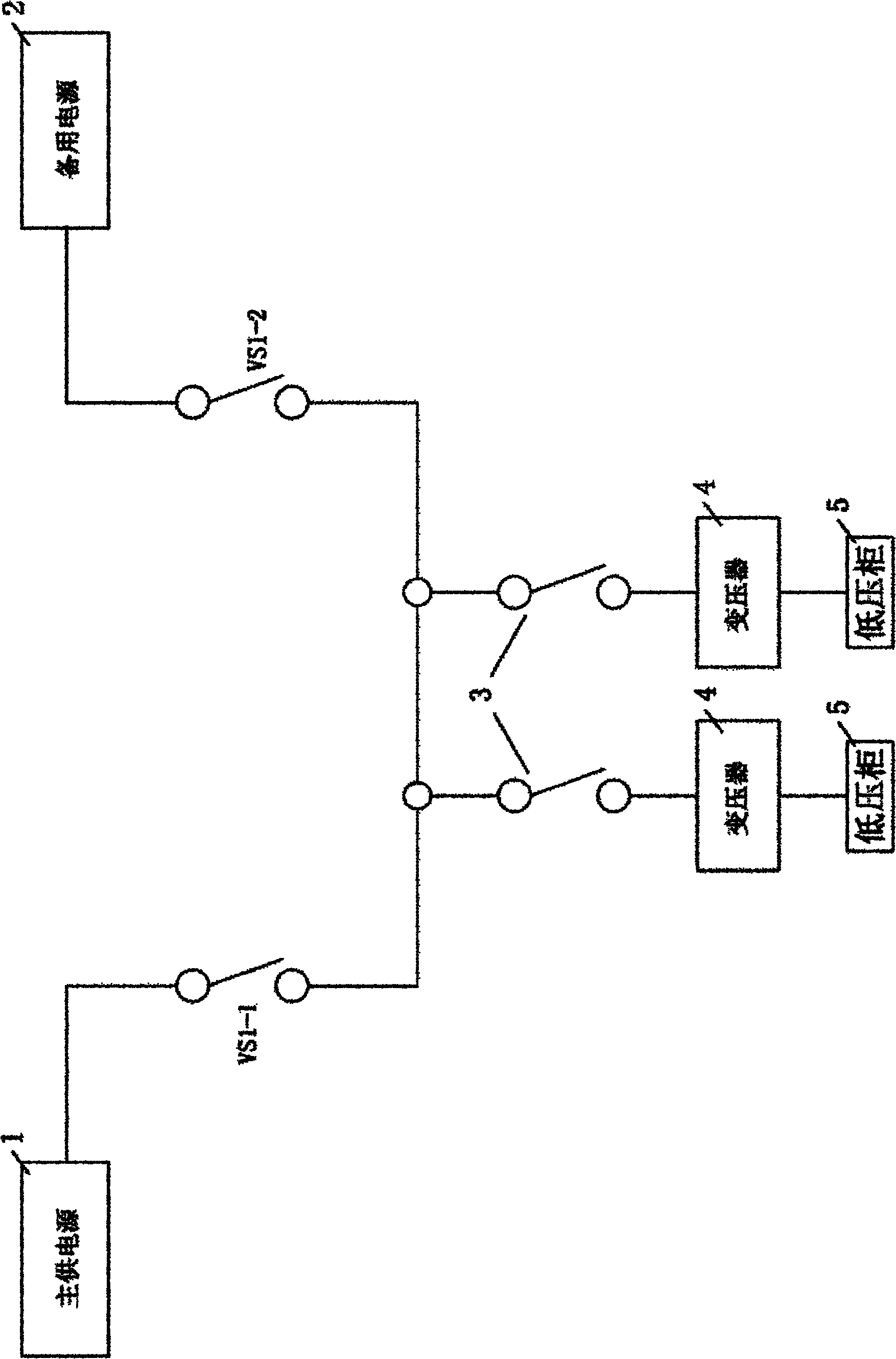
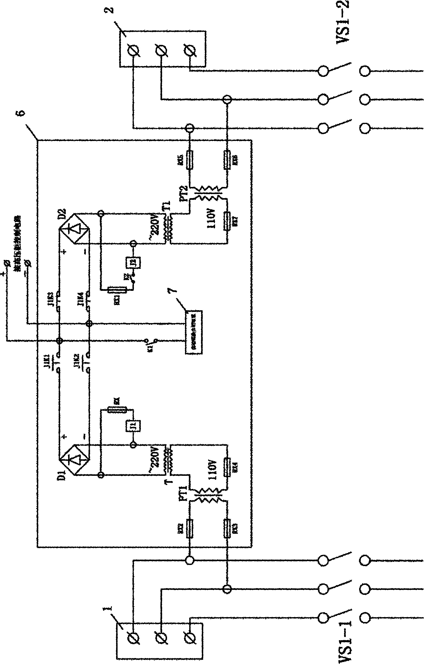
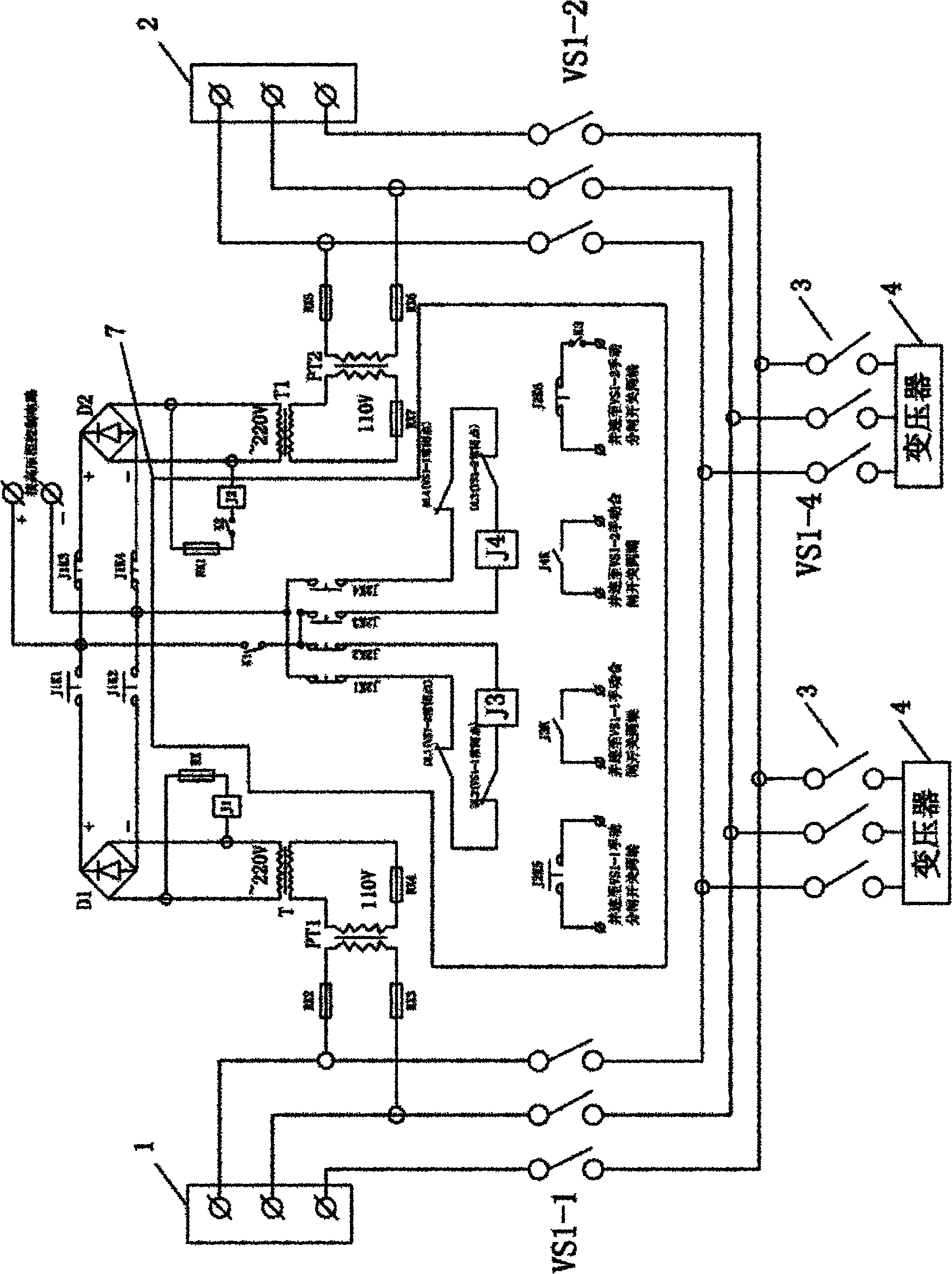
[0014] like figure 2 , image 3 As shown, the present invention includes a main power supply 1, a backup power supply 2 and a high-voltage cabinet control circuit. The main power supply 1 and the backup power supply 2 are respectively connected to the follow-up The outlet circuit breaker 3 and the transformer 4 are connected to the low-voltage cabinet 5. Between the main power supply 1 and the backup power supply 2 there are such figure 2 As shown in the self-power supply device 6, the self-power supply device 6 includes main and backup DC power supply branches. The main DC power supply branch circuit includes a main voltage transformer PT1 connected in parallel to the incoming line terminal of the main power supply source 1, the output end of the main voltage transformer PT1 is connected to the main intermediate isolation transformer T1, and the output end of the main intermediate isolation transformer T1 is parallel Connected with the coil of the main rectifier bridge D...


PUM


Abstract

The invention discloses a self-powered automatic switching and closing high-voltage control system, which comprises a main power supply, a spare power supply and a high-voltage cabinet control circuit, wherein a self-powered device is arranged between the main power supply and the spare power supply, and the self-powered device comprises main and spare direct-current power supply branches; the main and spare direct-current power supply branches comprise main and spare voltage transformers connected in parallel with the wire inlet ends of the main and spare power supplies respectively, the output ends of the main and spare voltage transformers are connected with main and spare middle isolating transformers respectively, the output end of the main middle isolating transformer is connected in parallel with coils of a main rectifying electric bridge and a direct-direct switching relay at the same time, the output end of the spare middle isolating transformer is connected with a spare rectifying electric bridge, and the output ends of the main and spare rectifying electric bridge are connected with the power supply input ends of the high-voltage cabinet control circuit and an automatic switching and closing device through contacts of the direct-direct switching relay. The system not only can provide uninterrupted power supply for the high-voltage cabinet control circuit, but also can realize automatic switching of the main and spare power supplies.

Description

technical field [0001] The invention relates to a high-voltage control system, in particular to a high-voltage control system with self-power supply and automatic switching and closing. Background technique [0002] In the power system, for important users or substations that require high power supply reliability, two or more power supplies must be provided. As a working power supply, the rest of the power supply is used as a backup mode of operation. At the same time, it is equipped with an automatic switching switching system for the standby power supply. When the working power supply fails for some reason, the automatic switching switching system for the standby power supply will quickly switch to the standby power supply, so that users or substations can regain power. However, the precondition of the automatic switching and closing function of the standby power supply is a reliable operating power supply, so a device for self-power supply is urgently needed. [0003] l...

Claims


Application Information

Patent Timeline
IPC IPC(8): H02J9/06
Inventor 黄新闻余庄平严健黄国兴
Owner HUNAN YANNENG SENYUAN ELECTRIC POWER EQUIP
Why Eureka
Try Eureka