
Method and device for photoelectrical hybrid clock recovery and optical transmission signal performance monitoring

A clock signal and signal technology, applied in optical fiber transmission, transmission monitoring/testing/fault measurement system, electromagnetic wave transmission system, etc., can solve problems such as inaccurate OSNR monitoring, large system size, and no FEC chip

Inactive Publication Date: 2013-08-21
TSINGHUA UNIV
View PDF3 Cites 0 Cited by
  • Summary
  • Abstract
  • Description
  • Claims
  • Application Information

AI Technical Summary

Problems solved by technology

[0009] The clock recovery and signal performance monitoring in the prior art are implemented by different functional modules respectively, which have problems such as high cost and large system volume, and it is difficult to effectively combine with clock recovery for the monitoring implementation scheme of other principles, and there are limited monitoring range, Low efficiency, easy to be affected by other factors and reduce the accuracy of monitoring, etc.
For example, a spectrum-based interpolation method is used to monitor the optical signal-to-noise ratio. If the wavelength channel is optically filtered, resulting in a large difference between the out-of-band noise power and the in-band noise power, the in-band noise estimated by interpolation is inaccurate, resulting in OSNR Monitoring is inaccurate; another example is the use of polarization extinction to monitor OSNR, its accuracy depends on the degree of polarization of the signal and noise, only when the degree of polarization of the signal is 1 and the degree of polarization of the noise is 0, can accurate results be obtained, but the polarization in transmission Both modal dispersion and polarization-dependent loss will destroy this condition; BER is used to monitor chromatic dispersion, and there are many factors that cause BER changes, it is difficult to determine whether it is caused by chromatic dispersion, and the system is required to have forward error correction (FEC) function, Once the bit error rate exceeds the error correction capability, the system cannot work normally
In addition, when the signal rate is very high, such as above 40Gbit / s, there is no suitable FEC chip at present, and high-speed devices are expensive and consume a lot of power

Method used


Image

  • Method and device for photoelectrical hybrid clock recovery and optical transmission signal performance monitoring
  • Method and device for photoelectrical hybrid clock recovery and optical transmission signal performance monitoring
  • Method and device for photoelectrical hybrid clock recovery and optical transmission signal performance monitoring

Examples


Embodiment Construction

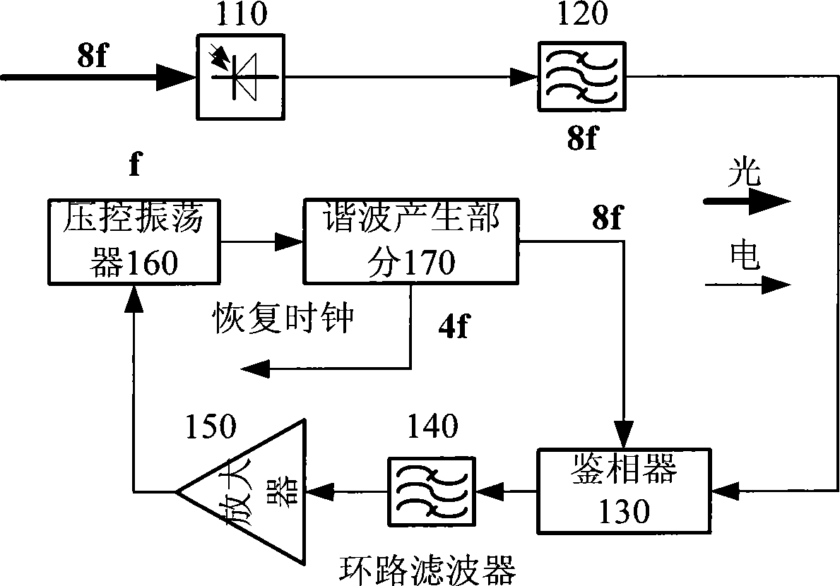
[0032] The present invention solves the above problems by combining clock recovery, and introduces an electro-optic modulator for frequency conversion, so that signal processing is performed at a lower frequency, thereby reducing the requirements for devices. In addition, in order to overcome the polarization-sensitive characteristics of the electro-optic modulator, A polarization diversity scheme is proposed to solve it.

[0033] According to one aspect of the present invention, there is provided a method for simultaneously realizing clock recovery of high-speed digital signals and performance monitoring of transmission signals based on photoelectric hybrid, which is characterized in that it includes:

[0034] The electro-optical modulator is used at the receiving end to reduce the frequency of the clock signal, thereby reducing the bandwidth and rate requirements for post-processing devices.

[0035] The performance of the optical transmission signal is monitored by using th...


PUM


Abstract

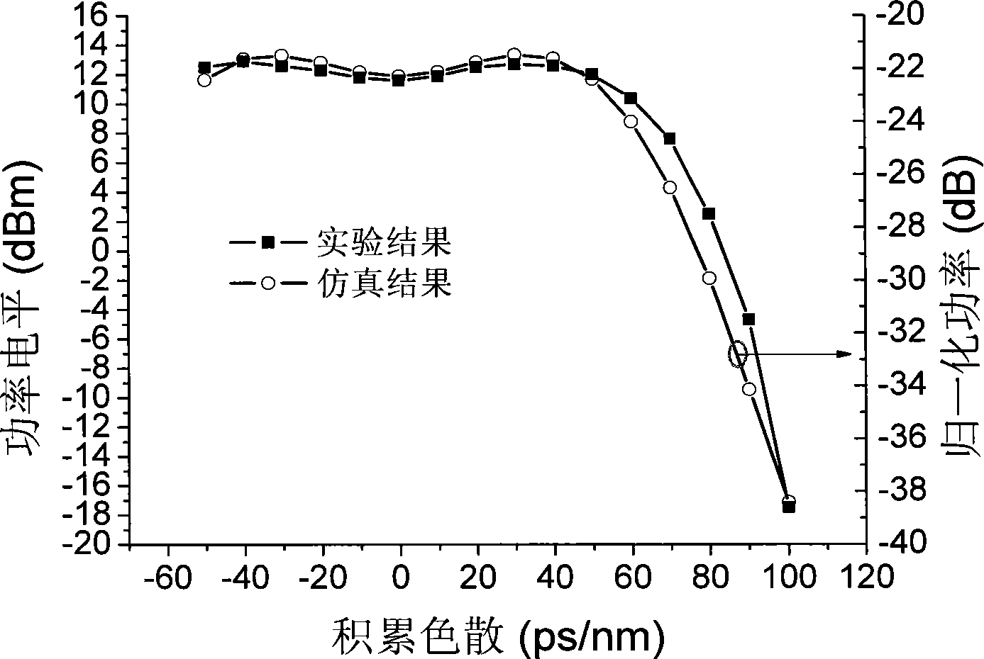
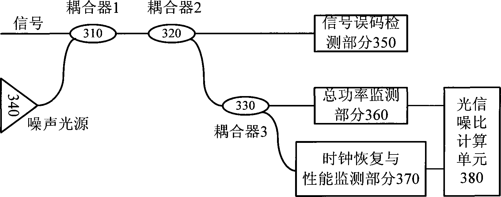
In the invention, clock recovery and optical transmission signal performance monitoring are combined, and the timing information of an optical transmission signal is extracted while the monitoring of signal accumulation dispersion and optical signal-to-noise ratio is realized. The method comprises the following steps of: performing optical domain frequency conversion to the timing information (clock) of the optical transmission signal by using an electrooptical modulator, and reducing the frequency of the clock to a lower frequency; and extracting the timing information by using a phase locked loop in the low frequency range, outputting a phase error signal in the phase locked loop by using an orthogonal phase discriminator and simultaneously outputting a direct-current level for representing the intensity of the timing information, wherein the variation rule of the level is used for monitoring the accumulation dispersion and the optical signal-to-noise ratio of the transmission signal. The invention also provides a clock extraction and performance monitoring system of a differential quaternary phase shift keying (DQPSK) system for implementing the method.

Description

technical field [0001] The invention relates to a method and device for clock recovery and signal performance monitoring required for high-speed optical transmission signal reception. Background technique [0002] Clock recovery is the operation of extracting the timing information reflecting the data change cycle from the data stream. It is an indispensable technology at the receiving end of the high-speed serial digital synchronous communication system and has attracted extensive attention. [0003] Transmission signal performance monitoring refers to the analysis of the characteristics of the transmission signal to evaluate the various damages and deterioration experienced during the signal transmission process, and to judge the change degree of the signal performance compared with that before transmission. Commonly used signal performance monitoring includes monitoring the optical signal-to-noise ratio, accumulated dispersion, differential group delay, polarization mode ...

Claims


Application Information

Patent Timeline
Patent Type & Authority Patents(China)
IPC IPC(8): H04B10/07H04B10/2507H04L7/033H04B10/077
Inventor 闻和程林郑小平张汉一
Owner TSINGHUA UNIV
Learn More