Al technical title is built by PatSnap Al team. It summarizes the technical point description of the patent document.
A vibrating mill and pendulum technology, applied in the direction of fluid and grain processing using vibration, can solve the problems of system loss of stability, anti-grinding, non-refinement, etc., to improve rapidity and reliability, reduce starting torque, The effect of preventing resonance
Inactive Publication Date: 2011-02-16
江华瑶族自治县金牛开发建设有限公司
View PDF6 Cites 5 Cited by
Summary
Abstract
Description
Claims
Application Information
AI Technical Summary
This helps you quickly interpret patents by identifying the three key elements:
Problems solved by technology
Method used
Benefits of technology
Problems solved by technology
[0004] However, the pendulum block of the ordinary vibrator is fixed on the shaft of the vibrator. Once the maximum exciting force is set, it will be a constant value during the operation process. However, during the start and stop process, when the vibration frequency is close to the system’s When the natural frequency is lower, the amplitude will increase rapidly and generate resonance, which not only makes the system lose stability, but also easily causes damage to the vibration machinery including the structure of the exciter itself
[0005] Ordinary vibrating mills (including extra-large vibrating mills, the same below) require the system to pass the resonance point smoothly during the start-stop phase to ensure the normal operation of the vibrating system; in many cases, the vibration generated by the vibrating mill system during the working process, It has chaotic vibration characteristics such as a wide power spectrum curve or some irregular properties of the motion track to complete some special operations, such as solving the problems of non-refining, easy agglomeration, and anti-crushing in ultra-fine and ultra-fine grinding. Solve technical problems such as low efficiency and high energy consumption when crushing superhard, hard, metal or non-metal brittle powders. The ordinary vibrating mill or other grinding equipment in the prior art is almost powerless to solve these problems
Method used
Image
Click on the blue label to locate the original text in one second.
Reading with bidirectional positioning of images and text.
Examples
Embodiment Construction
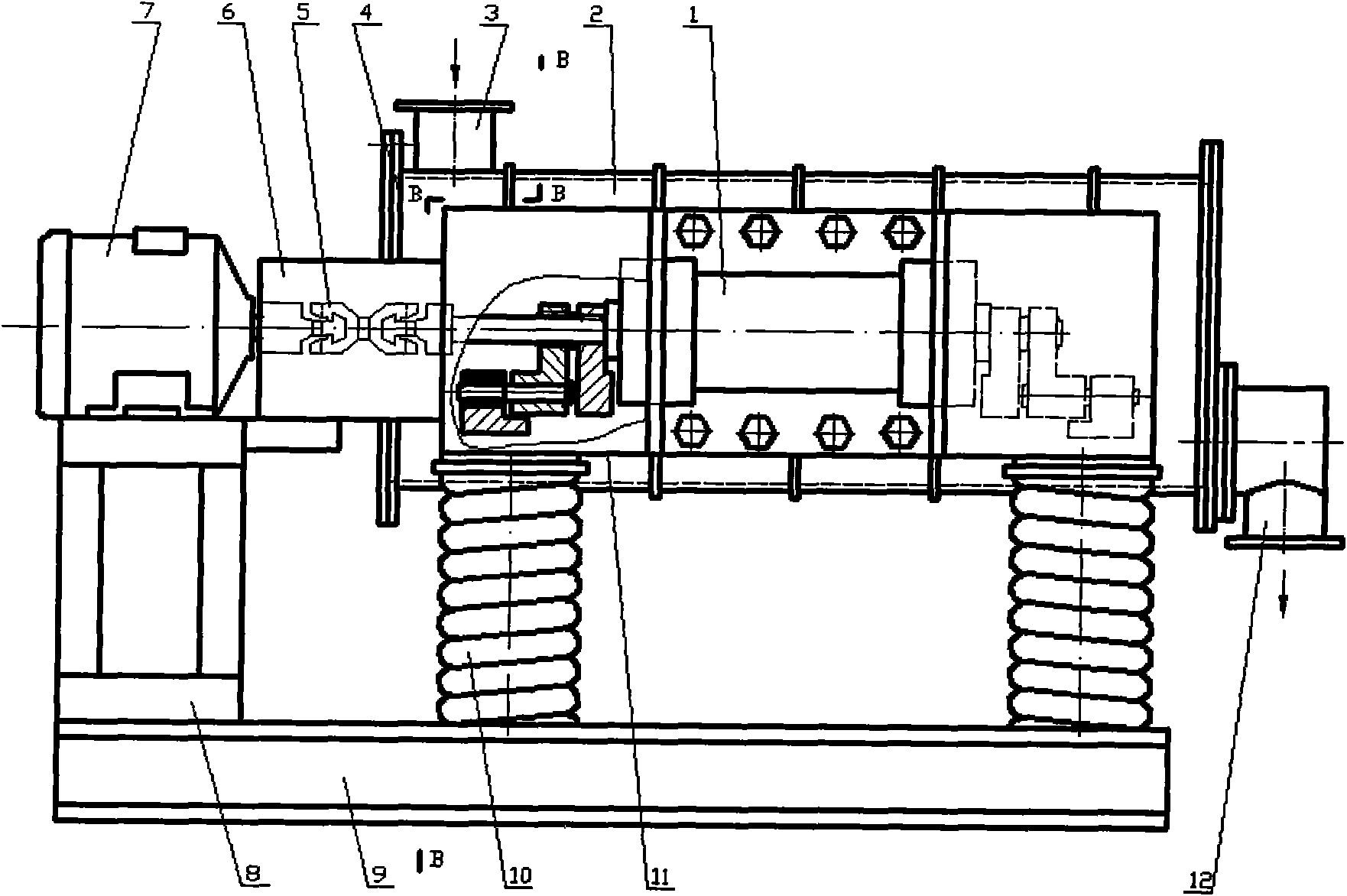
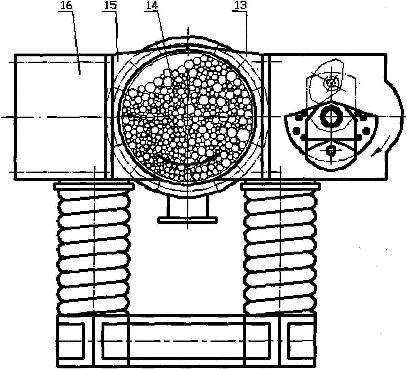
[0034] attached Figure 1-2 It is an embodiment of the present invention in the form of a single body structure, with Figure 1-2The secondary swinging chaotic vibrating mill includes vibrator 1, cylinder body 2, feed port 3, end cover 4, coupling 5, coupling cover 6, motor 7, motor base 8, base 9, screw Spring 10, swing cover 11, discharge port 12, right coupling frame 13, grinding medium 14, left coupling frame 15, counterweight body 16.
[0035] Refer to attached figure 1 , The vibration mass body of the present invention includes a vibrator 1, a cylinder body 2, a grinding medium 14, a counterweight body 16, and the like. In this embodiment, there is a cylinder, and the vibrator 1 is rigidly fixed on the right side of the cylinder 2 as the excitation source, and the cylinder 2 is excited on one side in a biased manner, that is, the axis of gravity and the center of gravity of the cylinder 2 In addition to its excitation, a counterweight 16 is set to balance the quality ...
PUM
Abstract
The invention discloses a secondary variable pendulum chaotic vibrating mill, relating to a vibrating mill capable of generating special inertia excitation capacity, in particular to a vibrating mill with special vibrating effect, chaotic vibrating characteristics and a secondary variable pendulum structure. The vibrating mill comprises a vibration excitor, a cylinder body, a feed inlet, end covers, a coupling, a motor, a motor seat, a base, a helical spring, a discharge outlet, a right connecting bracket, a milling medium, a left connecting bracket and a balance weight body, wherein the vibration excitor is rigidly fixed at the right side of the cylinder body through the right connecting bracket; the balance weight body is rigidly fixed at the left side of the cylinder body through the left connecting bracket; the lower parts of the cylinder body and the vibration excitor are installed on the base through the helical spring; the vibration excitor comprises a bearing seat assembly, a vibration excitor shaft and a secondary variable pendulum assembly; the motor is connected with the vibration excitor shaft through the coupling; the secondary variable pendulum assembly comprises an invariable pendulum, a primary variable pendulum, a secondary variable pendulum, a secondary variable pendulum shaft, a bearing I and a bearing II; and the cylinder body is provided with the feed inlet and the discharge outlet, the end covers are installed at two sides of the cylinder body, and the milling medium is installed in the cylinder body.
Description
technical field [0001] The invention relates to a two-stage swing chaotic vibrating mill, which relates to a vibrating mill capable of producing special inertial vibration, especially a vibrating mill with a special vibration effect and chaotic vibration characteristics, and a two-stage swinging structure, which belongs to the vibration utilization project technology field. Background technique [0002] Vibrating mill is a vibrating mechanical equipment that uses the principle of vibration to complete material crushing operations. Ordinary vibrating mills are composed of one or more cylindrical containers supported on springs. Ordinary vibrator or vibrating motor, vibrating unbalanced movement, the grinding medium installed in the mill container collides and rubs against the material to be ground, and the crushing is due to the grinding medium itself, the grinding medium, the material, and the wall of the container. The result of the collision and friction between them. Th...
Claims
Application Information
Patent Timeline
Application Date:The date an application was filed.
Publication Date:The date a patent or application was officially published.
First Publication Date:The earliest publication date of a patent with the same application number.
Issue Date:Publication date of the patent grant document.
PCT Entry Date:The Entry date of PCT National Phase.
Estimated Expiry Date:The statutory expiry date of a patent right according to the Patent Law, and it is the longest term of protection that the patent right can achieve without the termination of the patent right due to other reasons(Term extension factor has been taken into account ).
Invalid Date:Actual expiry date is based on effective date or publication date of legal transaction data of invalid patent.