Supercharge Your Innovation With Domain-Expert AI Agents!

Die matching device of liquid flow suspension ultraprecise cylinder polishing head

A polishing head and cylinder technology, applied in the direction of grinding devices, grinding/polishing equipment, metal processing equipment, etc., can solve the problems of reduced processing quality, affecting the uniformity of polishing, and long processing time, so as to reduce runout errors , Guarantee the effect of uniformity and high processing precision

Active Publication Date: 2012-06-27
ZHEJIANG UNIV OF TECH
View PDF0 Cites 0 Cited by
  • Summary
  • Abstract
  • Description
  • Claims
  • Application Information

AI Technical Summary

Problems solved by technology

The traditional matching mold uses the mold cavity to pour and form, and produces a cylindrical polishing head assembled on the processing rod connected to the motor head, which has the following disadvantages: 1. The cylindricity accuracy of the cylindrical polishing head after the matching mold is low, and the diameter The circular runout is large, and the gap between the cylindrical polishing head and the workpiece cannot reach the micron level at all, so that the cylindrical polishing head in processing is in contact with the workpiece; Parallel, so that the cylindrical polishing head forms a small angle with the transmission shaft during high-speed rotation, which affects the uniformity of polishing; 3. The surface roughness of the cylindrical polishing head depends on the roughness of the inner surface of the mold in the traditional mold matching process. However, the roughness of the outer surface of the cylindrical polishing head has a certain influence on the dynamic pressure of the liquid in the polishing liquid, which eventually leads to too long processing time, reduced processing quality and increased cost.

Method used


Image

  • Die matching device of liquid flow suspension ultraprecise cylinder polishing head
  • Die matching device of liquid flow suspension ultraprecise cylinder polishing head

Examples


Embodiment Construction

[0018] The present invention will be further described below in conjunction with accompanying drawing:

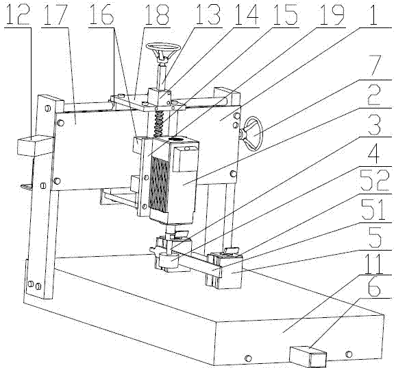
[0019] refer to figure 1 , the mold matching device of the liquid flow suspension ultra-precision cylindrical polishing head of the present invention includes a computer numerical control module 1 for eliminating the return error of the transmission screw 15, and the computer numerical control module 1 includes an X on the machine tool 6 To the stepper motor 11, Y to the stepper motor 12 and Z to the stepper motor 13, the described Z to the stepper motor 13 is connected with a shaft coupling 14, and the described shaft coupling 14 is connected with a transmission lead screw 15. The transmission lead screw 15 is provided with a slider 16 for adjusting its position, and the slider 16 is mated with the X-direction cage 17, the Y-direction cage 18 and the Z-direction cage 19, and the One side of the Z-direction cage 19 is fixed with a high-speed motor 2 for driving the process...


PUM


Abstract

The invention relates to a die matching device of a liquid flow suspension ultraprecise cylinder polishing head, comprising a computer numerical control module for eliminating hysteresis errors of a transmission lead screw. The computer numerical control module comprises an X-direction stepping motor, a Y-direction stepping motor and a Z-direction stepping motor; the Z-direction stepping motor isconnected with a coupling which is connected with the transmission lead screw; the transmission lead screw is provided with a sliding block for adjusting the position thereof; the sliding block is connected with an X-direction retainer, a Y-direction retainer and a Z-direction retainer in a matching manner; one side of the Z-direction retainer is fixedly provided with a high-speed motor for driving a processing rod to rotate at high speed; the processing rod is connected below the high-speed motor and is provided with an elastic cylinder polishing head rotating at high speed by interference; and the cylinder polishing head is contacted with a rounding surface on a rounding processing device for removing redundant materials on the surface. The die matching device has the advantages of simple structure, high processing accuracy and lower cost.

Description

technical field [0001] The invention relates to a polishing tool mold matching and forming device in the field of precision machining, which is particularly suitable for accurate mold matching of a cylindrical polishing head in liquid flow suspension ultra-precision machining experiments. Background technique [0002] At present, the finishing process of grooves, special-shaped curved surfaces and corner-clearing parts of complex cavities of precision molds is still mainly manual grinding and polishing, which cannot be strengthened at the same time, resulting in poor processing capacity, low production efficiency, and high production costs. Guarantee the processing quality. The liquid suspension ultra-precision machining technology uses the high-speed rotation of the cylindrical polishing head in the processing fluid, and with the help of hydrodynamic pressure, the free abrasive particles in the processing liquid are continuously shot towards the surface of the workpiece. T...

Claims


Application Information

Patent Timeline
Patent Type & Authority Patents(China)
IPC IPC(8): B24D18/00
Inventor 洪滔何剑敏侯海鹏王超荣於加峰
Owner ZHEJIANG UNIV OF TECH
Features
  • R&D
  • Intellectual Property
  • Life Sciences
  • Materials
  • Tech Scout
  • Unparalleled Data Quality
  • Higher Quality Content
  • 60% Fewer Hallucinations
Learn More