Supercharge Your Innovation With Domain-Expert AI Agents!

A High Precision Grinding Technology and Application of Slender Shaft

A slender shaft, high-precision technology, applied in the direction of machine tools, grinding/polishing equipment, grinding machines, etc. designed for grinding the rotating surface of workpieces, it can solve the problems of spline hole quality, poor machining accuracy, coaxial To avoid problems such as poor degree of accuracy, to achieve good use effect and reduce jumping error

Active Publication Date: 2020-07-14
JIANGYIN SAITE PRECISION TOOL
View PDF9 Cites 0 Cited by
  • Summary
  • Abstract
  • Description
  • Claims
  • Application Information

AI Technical Summary

Problems solved by technology

Such a broach can be tested in the factory, but it is unqualified to pull the spline hole in the gear factory. This kind of processing error seriously affects the quality of the broach, and even affects the quality of the spline hole of the part.
[0006] Traditional process 2: Grinding the outer circle does not use the center frame to support the fixture but directly grinds the outer circle, forming a new shape error, which destroys the regular arrangement of the cutting edge of the broach, and the out-of-roundness of the outer circle reference leads to subsequent machining accuracy become worse
[0007] In addition, when processing slender shaft parts such as ball screws, precision slender screws, and polished rods, there will also be technical problems such as difficulty in adjusting the slender shaft and resulting in out-of-tolerance coaxiality

Method used


Image

  • A High Precision Grinding Technology and Application of Slender Shaft
  • A High Precision Grinding Technology and Application of Slender Shaft
  • A High Precision Grinding Technology and Application of Slender Shaft

Examples


Embodiment 1

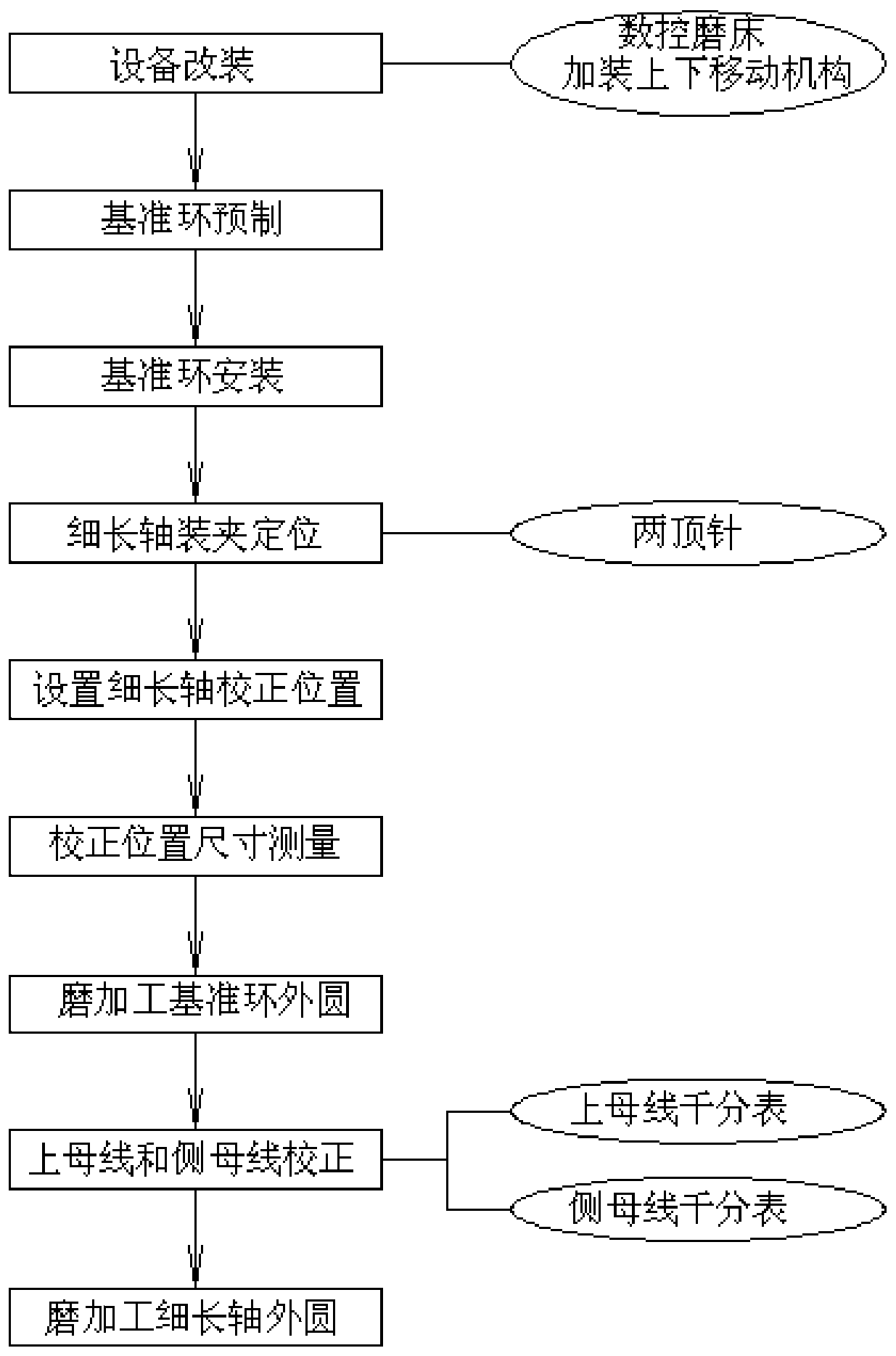
[0043] Such as Figures 1 to 3 Shown is the embodiment of the high-precision grinding process and application of a kind of slender shaft of the present invention, including the following process steps:

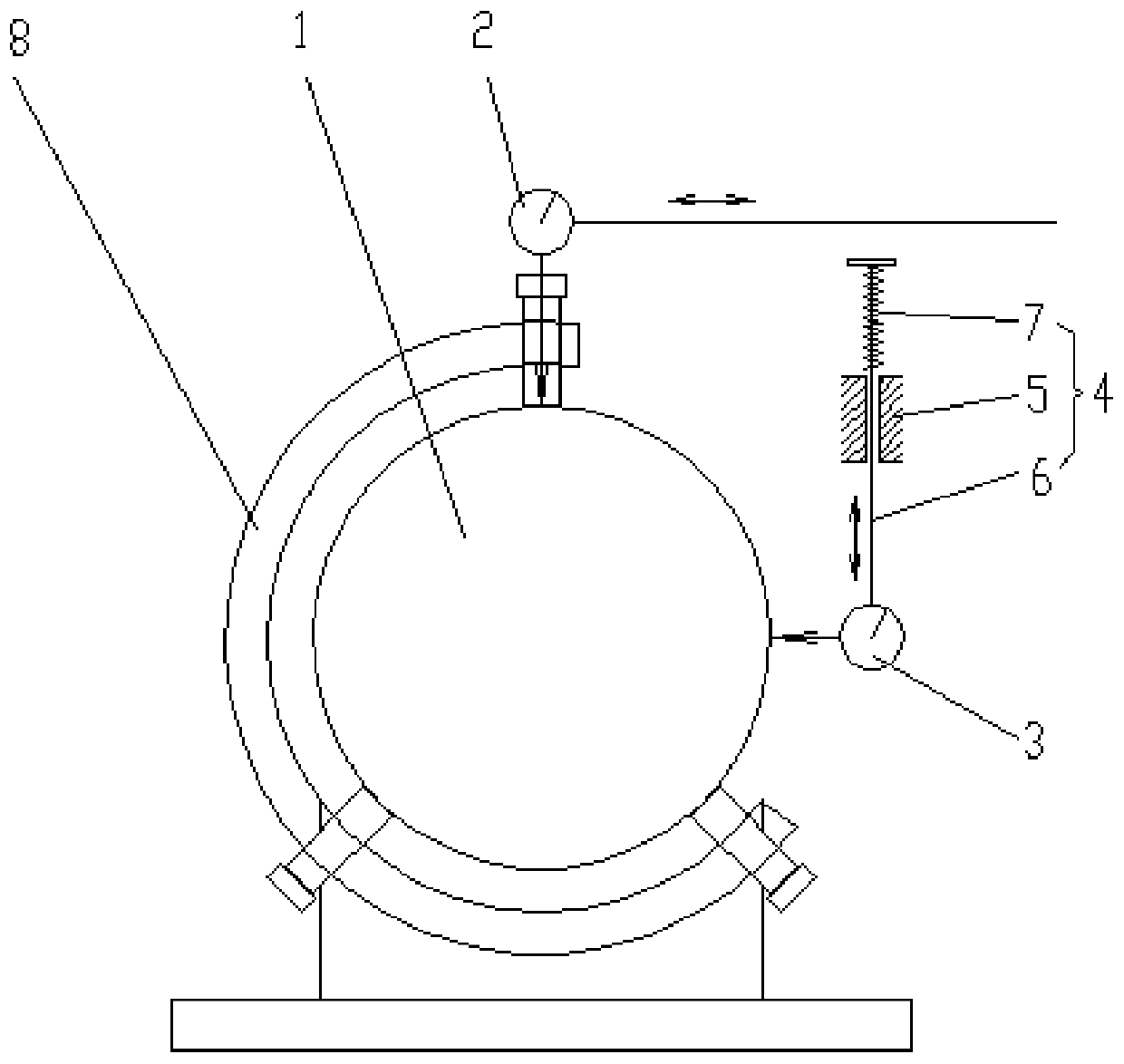
[0044] (1) Equipment refitting: a CNC cylindrical grinder is used as the equipment for cylindrical grinding of the slender shaft, and an upper bus bar dial indicator 2 for correcting the bus bar on the slender shaft 1 is installed on the grinding wheel headstock of the CNC cylindrical grinder; Simultaneously, install up and down moving mechanism 4 on the grinding wheel headstock of CNC cylindrical grinder, and install the side bus bar dial indicator 3 for correcting the side bus bar of slender shaft 1 on the moving arm 6 of described up and down moving mechanism 4;

[0045] (2) Reference ring prefabrication: Prefabrication of a reference ring matching the outer circle of one end of the slender shaft is used as a calibration tool for grinding the slender shaft, and the inner ho...

Embodiment 2

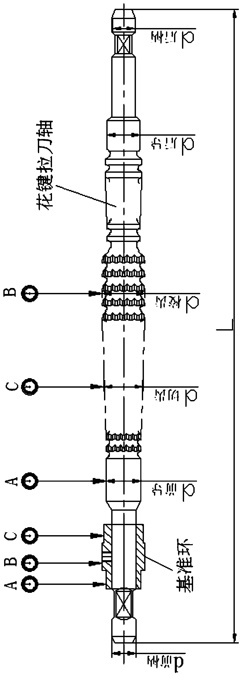
[0065] An application of the high-precision grinding process of the slender shaft of Embodiment 1, including applying the grinding process to grinding the outer circle of the spline broach shaft, and grinding the outer circle of the spline broach shaft After the grinding is completed, use a spline grinder to grind the tooth profile of the spline broach shaft, and before grinding the tooth profile of the spline broach shaft, use the reference ring and the center frame to pre-calibrate the upper generatrix of the outer circle of the tooth profile. , Side generatrix and radial circular runout are corrected to ensure that the outer circle of the N gear on the spline broach shaft is coaxial and the same size as the N gear outer circle on the reference ring.

[0066] Preferably, when grinding the tooth shape of the involute spline broach, the support point of the center frame is generally arranged on the leading outer circle of the broach and the specially ground roundness and radial...


PUM


Abstract

The invention relates to the technical field of thin and long shaft machining, and discloses a thin and long shaft high-precision grinding process and an application. The grinding process comprises the process steps of carrying out equipment modification, carrying out reference ring prefabricating, carrying out reference ring installation, carrying out clamping and positioning of a thin and long shaft, carrying out setting of the long and thin shaft correcting position, carrying out correcting position dimension measuring, carrying out grinding machining of an outer circle of a reference ring,carrying out upper bus and side bus correction, carrying out grinding machining of an outer circle of the thin and long shaft and the like, in the equipment modification working procedure, a numerical control outer circle grinding machine is adopted as equipment for grinding the outer circle of the long and thin shaft, and an upper bus dial indicator used for correcting an upper bus of the long and thin shaft is installed on a grinding wheel main shaft box of the numerical control outer circle grinding machine; and meanwhile, an up-down moving mechanism is additionally arranged on the grinding wheel main shaft box of the numerical control outer circle grinding machine, and a side bus dial indicator for correcting a side bus of the thin and long shaft is installed on a moving arm of the up-down moving mechanism. According to the process and the application, the grinding machining precision of the thin and long shaft part is improved.

Description

technical field [0001] The invention relates to the technical field of slender shaft processing, in particular to a high-precision grinding process and application of a slender shaft. Background technique [0002] With the development of the machinery industry, the promotion of intelligent technology, and the increasing popularity of CNC machine tools, the annual demand for slender shaft parts such as ball screws, precision slender screws, and polished rods is increasing year by year. Due to the large aspect ratio of this kind of slender shaft parts, it is easy to deform during processing. Especially when the aspect ratio of the slender shaft is greater than 50, the processing difficulty is greatly increased, the processing efficiency is greatly reduced, and the processing accuracy is very low. Difficult to guarantee. Therefore, solving the problem of high-quality machining and high-efficiency machining of slender shafts has always been a difficult problem that those skille...

Claims


Application Information

Patent Timeline
Patent Type & Authority Patents(China)
IPC IPC(8): B24B1/00B24B5/36
CPCB24B1/00B24B5/36
Inventor 吴海波杨涛黄炯
Owner JIANGYIN SAITE PRECISION TOOL
Features
  • R&D
  • Intellectual Property
  • Life Sciences
  • Materials
  • Tech Scout
  • Unparalleled Data Quality
  • Higher Quality Content
  • 60% Fewer Hallucinations
Learn More