Three-dimensional observation device for scouring terrain

A technology for observation devices and topography, which is applied in the direction of measuring devices, camera devices, measuring instruments, etc., can solve problems such as scoured terrain by difficult river engineering models, and achieve high observation efficiency and observation accuracy

Inactive Publication Date: 2011-02-16
DALIAN UNIV OF TECH
View PDF5 Cites 21 Cited by
  • Summary
  • Abstract
  • Description
  • Claims
  • Application Information

AI Technical Summary

Problems solved by technology

The three-dimensional landform observation method and device such as Xu Xiangzhou first applied the structured light measurement method to the real-time observation of the three-dimensional landform by gravity erosion of the slope (Xu Xiangzhou, Xu Feilong, Zhao Chao, Wang Shufang, Zhang Hongwu, three-dimensional landform observation device, Chinese invention patent, application number: 201010144655.8, 2010-4-12. Xu Xiangzhou, Xu Feilong, Zhao Chao, Xu Yi, Guo Xiangyang, three-dimensional landform observation method, Chinese invention patent, application number: 201010144689.7, 2010-4-12.), the observation device has a certain Observation accuracy and high observation efficiency, but it is difficult to apply to the scour terrain of the river engineering model, especially the terrain observation of scour pits

Method used


Image

  • Three-dimensional observation device for scouring terrain
  • Three-dimensional observation device for scouring terrain
  • Three-dimensional observation device for scouring terrain

Examples


Embodiment 1

[0030] The specific steps of the scour terrain observation method are as follows:

[0031] step 1

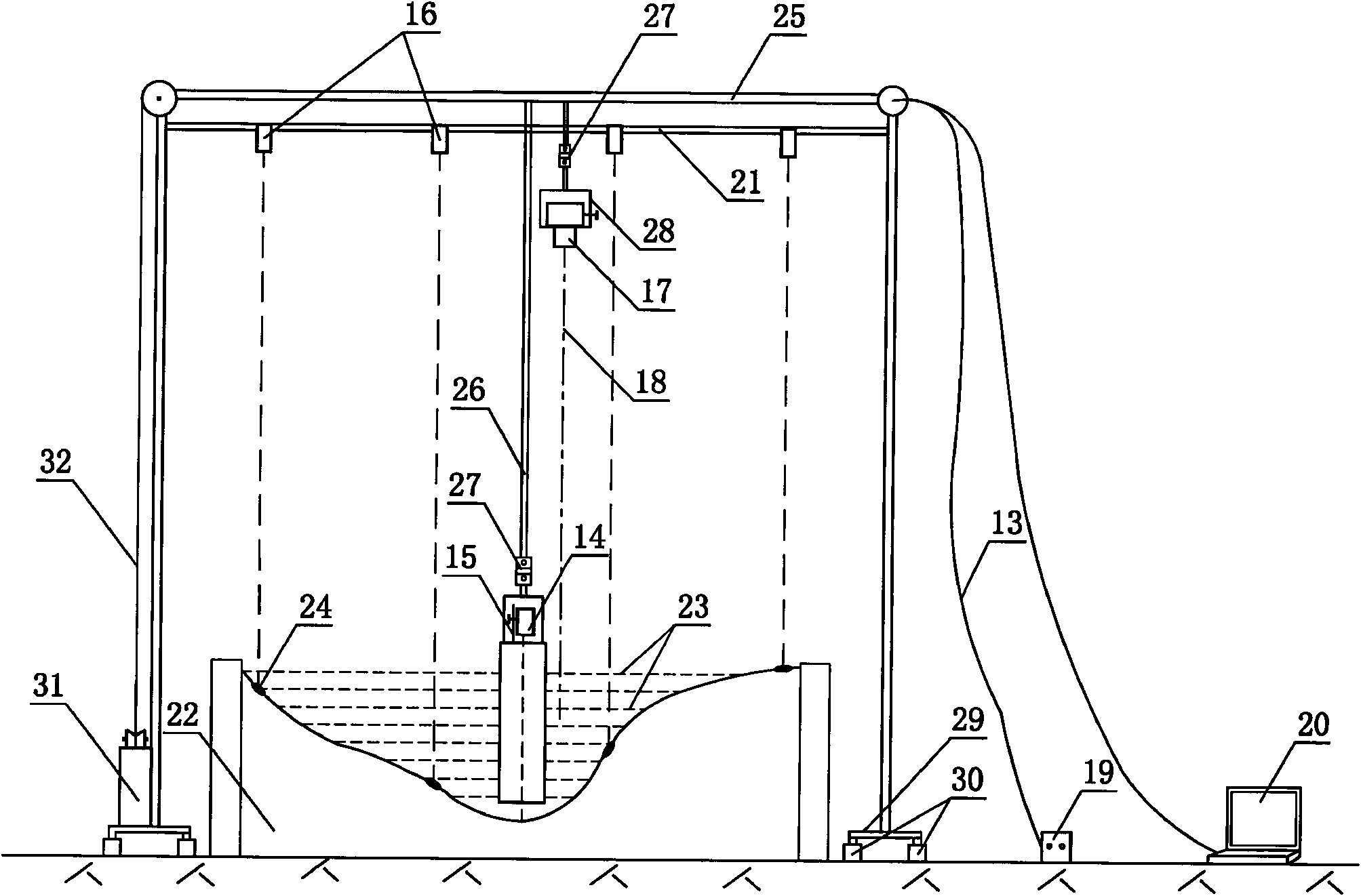
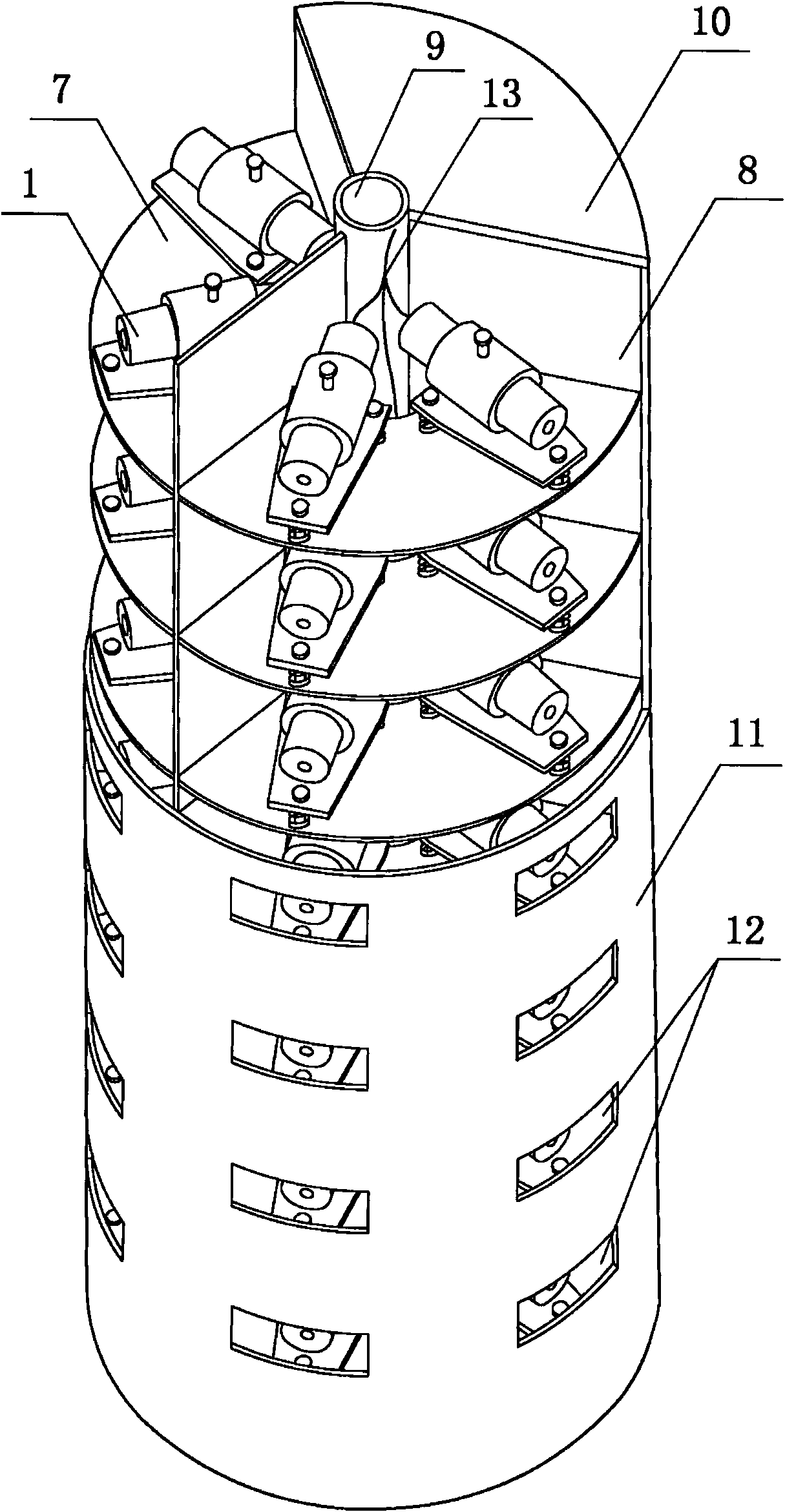
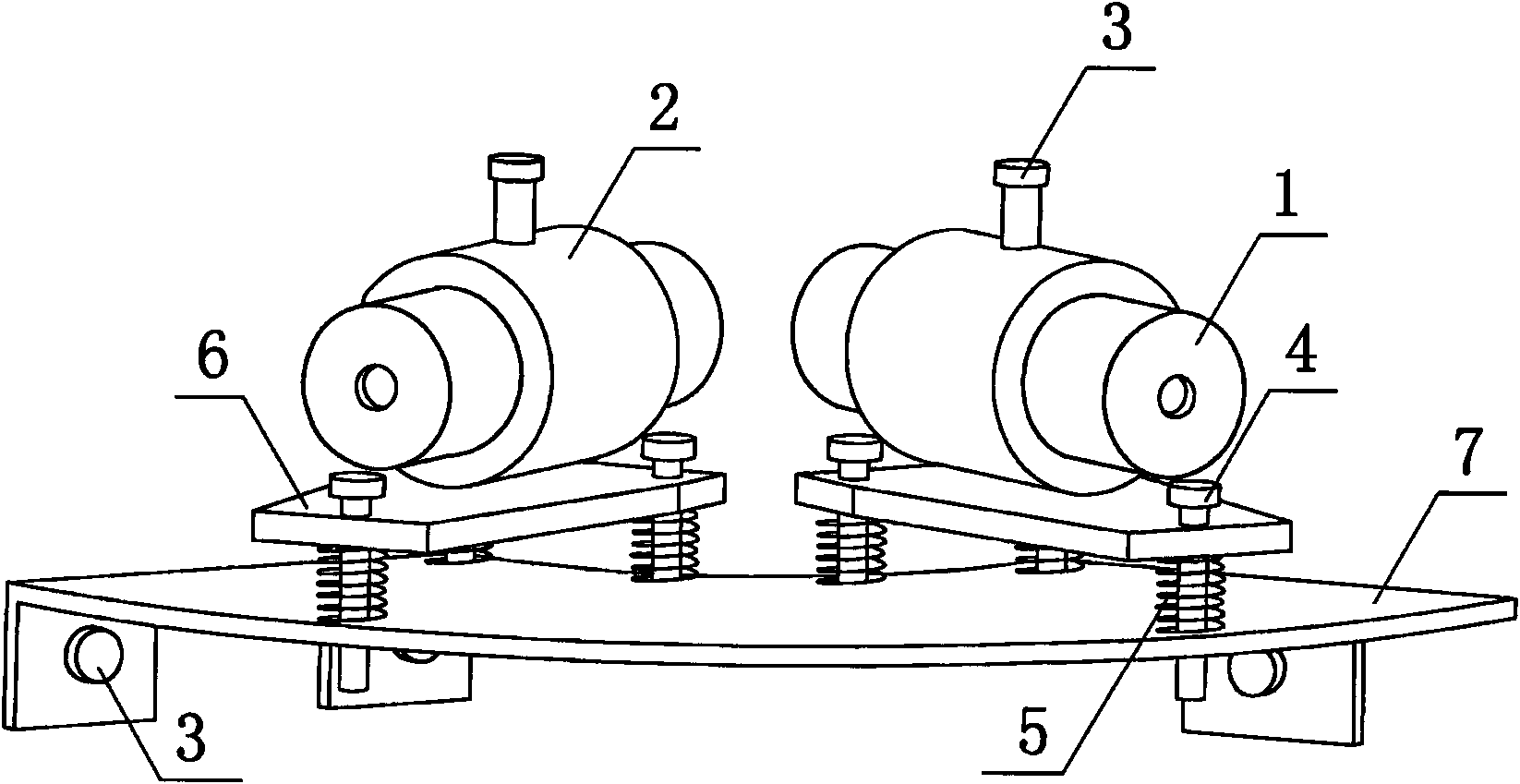
[0032] Install the full-plane laser projector, adjust it to a suitable viewing height, and turn on the power to make the full-plane laser projector emit a group of horizontal full-plane lasers 23 to its surrounding space terrain. The full-plane laser projector is connected and fixed with the support 25 through the connecting rod 26, and automatically adjusts the horizontal angle of the full-plane laser 23 through the universal joint 27 under the action of its own weight, so that the full-plane laser is parallel to the horizontal plane. Multiple sets of linear laser modules 1 in the full-plane laser projector emit a group of parallel full-plane lasers 23 with known spacing and parallel to each other through the laser exit hole 12 on the side cover 11 to the scoured terrain 22 after being powered on. Intersecting the surface of scour topography 22 forms a set of clearly visible las...


PUM


Abstract

The invention relates to a three-dimensional observation device for scouring terrain, belonging to the field of terrain measurement and comprising a full-plane laser projector, an image collection device, a terrain image calibration device, a host lifting device, a fixed support structure and a power supply system, wherein the full-plane laser projector comprises a slot-shaped line type laser die set, a die set micro-adjusting bracket, a baffle board, a cover board, a laser distance meter and a universal joint; the terrain image calibration device comprises a spot type laser die set and a fixed supporting board; the image collection device comprises a computer, a digital camera, a camera gravity positioning box and a universal joint; the respective horizontal angle of the full-plane laser projector and the digital camera is automatically adjusted through the universal joint under the self-weight action so that the full-plane laser is in parallel to a horizontal plane; the principal optical axis of the camera is perpendicular to the horizontal plane; and the host lifting device controls the lifting of the full-plane laser projector in a step pitch setting mode. The integral set of the system has higher observation efficiency and precision, and is suitable for the research on the aspect of terrain three-dimensional analysis in a river model test.

Description

technical field [0001] The invention belongs to the technical field of topographical measurement and relates to a device for topographical observation of scoured river engineering models. Background technique [0002] In the field of topographic surveying, the traditional surveying method is single-point contact surveying with a level gauge and a theodolite. The non-contact measurement method shows its great application potential in practice. At present, in the research of river engineering models at home and abroad, in addition to the traditional observation techniques, the commonly used topographic observation techniques mainly fall into the following three categories: [0003] The first type, laser ranging technology, by emitting pulsed laser beams to the target surface and receiving the laser beams returned through the target surface, the distance between the object surface point and the range finder is accurately measured by the principle of light speed in the air as a...

Claims


Application Information

Patent Timeline
Patent Type & Authority Applications(China)
IPC IPC(8): G01C15/00G01C11/00G01C11/02
CPCY02A90/30
Inventor 徐向舟徐飞龙刘亚坤王书芳
Owner DALIAN UNIV OF TECH
Why Eureka
Try Eureka