Isolated bidirectional DC-DC converter realized by coupling inductor

A technology of DC converters and coupled inductors, which is applied in the direction of converting DC power input to DC power output, adjusting electrical variables, and high-efficiency power electronics conversion. It can solve problems such as reducing system power density, increasing transformer volume, and affecting system power levels. , to achieve the effect of reducing volume, improving efficiency, and simple circuit structure

Active Publication Date: 2011-02-16
HOYMILES POWER ELECTRONICS INC
View PDF3 Cites 25 Cited by
  • Summary
  • Abstract
  • Description
  • Claims
  • Application Information

AI Technical Summary

Problems solved by technology

[0008] 3. In this scheme, the forward transformer only transfers energy to the high-voltage side when its corresponding switch tube is turned on, while the flyback transformer only transfers energy to the high-voltage side when its corresponding switch tube is turned off, resulting in low utilization of the transformer , which increases the volume of the transformer and reduces the system power density;
[0009]4. Due to the asymmetry of the forward transformer and the flyback transformer, it is difficult to realize the interleaved parallel operation of the circuit, which affects the improvement of the system power level

Method used


Image

  • Isolated bidirectional DC-DC converter realized by coupling inductor
  • Isolated bidirectional DC-DC converter realized by coupling inductor
  • Isolated bidirectional DC-DC converter realized by coupling inductor

Examples


Embodiment Construction

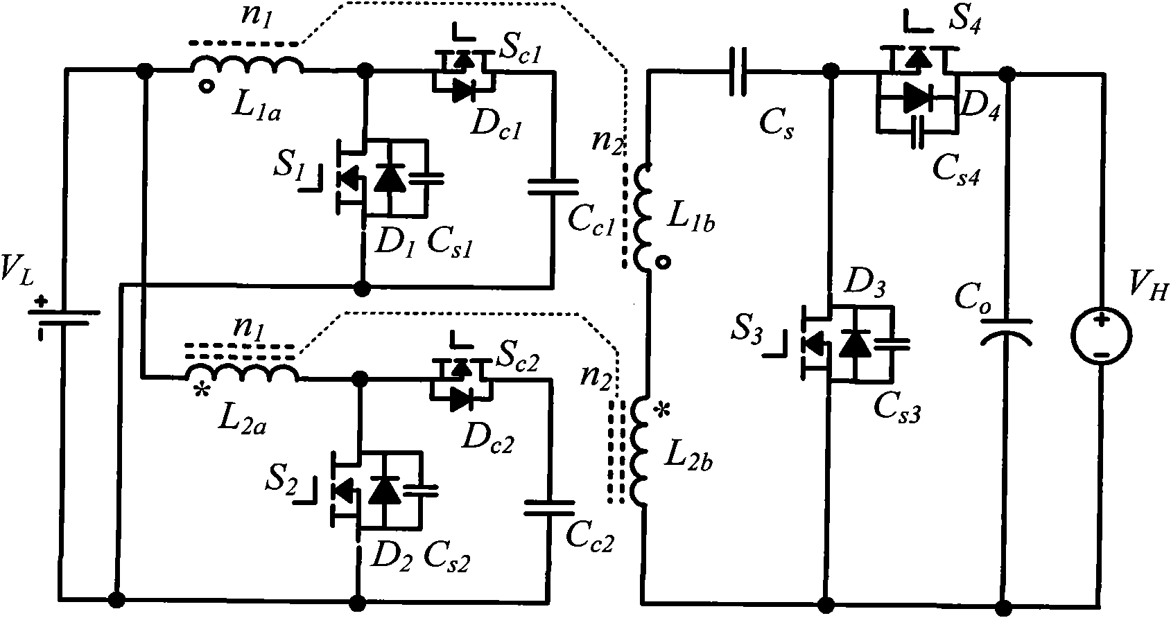
[0027] see figure 1 , the coupling inductor of the present invention implements an isolated bidirectional DC-DC converter, including a low-voltage side circuit and a high-voltage side circuit;

[0028] The low-voltage side circuit includes: two active clamping circuits and two L Parallel branches, the first parallel branch is routed by the first low-voltage side winding L 1a with anti-parallel diode D 1 The first power switch S 1 constituted in series, in the first power switch S 1 The first parallel capacitor C is connected in parallel at both ends S1 , the second parallel branch is routed by the second low-voltage side winding L 2a with anti-parallel diode D 2 The second power switch S 2 constituted in series, in the second power switch tube S 2 A second parallel capacitor C is connected in parallel at both ends S2 ; figure 1 In the example shown, the first active clamp circuit is connected in parallel with the first power switch tube S 1 on the source and drain, ...


PUM


Abstract

The invention discloses an isolated bidirectional DC-DC (direct current) converter realized by a coupling inductor, which comprises four power switch tubes with reverse parallel diodes and parallel capacitors, two auxiliary switch tubes with reverse parallel diodes, two clamping capacitors, a switch capacitor and two two-winding coupling inductors. The invention reduces the ripples of the low-voltage side current through the low-voltage side parallel structure, realizes the zero voltage shutoff of the power switch tubes through the parallel capacitors on the power switch tubes, realizes the zero voltage conduction of the power switch tubes through the leakage inductance of the coupling inductors, realizes lossless transfer of the leakage inductance energy through the auxiliary switch tubes and an active clamping circuit consisting of the reverse parallel diodes of the auxiliary switch tubes and the clamping capacitors, and increases/decreases the voltage of the converter through the serial structure of the high-voltage side windings of the two coupling inductors. The circuit has simple structure, all power switches work in a soft switch state, no energy consumption element is arranged in the circuit, and the converter efficiency is improved; and moreover, during the current conversion, the switch device does not experience voltage overshoot.

Description

technical field [0001] The invention relates to a bidirectional direct current-direct current converter, in particular to a bidirectional direct current-direct current converter realized by coupling inductance. Background technique [0002] In recent years, with the massive consumption of traditional energy such as oil and coal, energy shortage and environmental pollution have become the focus of the world, and the development and application of renewable energy have attracted widespread attention from all over the world. In the renewable energy power generation system, the electric energy generated by renewable energy such as wind energy and solar energy has a short-term fluctuation problem, and an energy storage system is required to make the energy output of the power generation system stable. Among them, the core of the energy storage system is a bidirectional DC-DC converter, which can store excess energy in energy storage devices such as batteries when the power genera...

Claims


Application Information

Patent Timeline
Patent Type & Authority Applications(China)
IPC IPC(8): H02M3/315
CPCY02B70/1491Y02B70/10
Inventor 何湘宁吴海蒙李武华赵一
Owner HOYMILES POWER ELECTRONICS INC
Why Eureka
Try Eureka