Stacked conduit assembly and screw fastening method for conduit part

A technology of assembly and pipeline, applied in the direction of circuit, thin plate connection, connecting components, etc., can solve the problems of cost increase, processing process increase, unfavorable thinning, etc., and achieve the effect of cost reduction

Inactive Publication Date: 2012-12-12
MITSUBISHI ELECTRIC CORP
View PDF1 Cites 0 Cited by
  • Summary
  • Abstract
  • Description
  • Claims
  • Application Information

AI Technical Summary

Problems solved by technology

[0006] However, in the method of forming screw holes by machining after the above-mentioned pipe parts are integrated, the cutting oil used in the screw hole processing and the cleaning fluid for removing the cutting oil flow into the pipe parts of the parts and cannot be fixed. The problem of removal is that in the case of small equipment, it is difficult to realize the avoidance area of ​​the drill tip in the bottom hole processing of the screw due to the arrangement where the position of the screw hole overlaps with the position of the inner layer pipe. The problem of thinning
[0007] As for the method of pre-processing a screw hole on a pipeline part and then integrating it, the simplest configuration to make the shape of the part is to separate the side wall of the pipeline from the top and bottom parts. However, since the thickness of each part is limited below the height of the pipeline in this case, it is difficult to obtain the necessary screw engagement length (usually more than three pitches of the thread teeth are required)
[0008] On the other hand, in the method described in Patent Document 1, the processing steps are increased and the cost is increased when forming the disk-shaped constriction, and the formation of the disk-shaped constriction is not conducive to thinning, so it is not an effective improvement method.

Method used


Image

  • Stacked conduit assembly and screw fastening method for conduit part
  • Stacked conduit assembly and screw fastening method for conduit part
  • Stacked conduit assembly and screw fastening method for conduit part

Examples


Embodiment approach 1

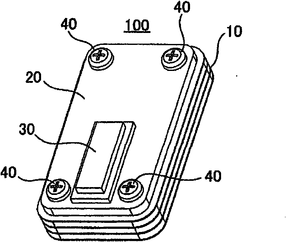
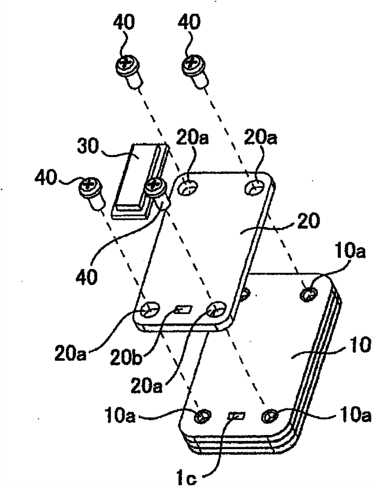
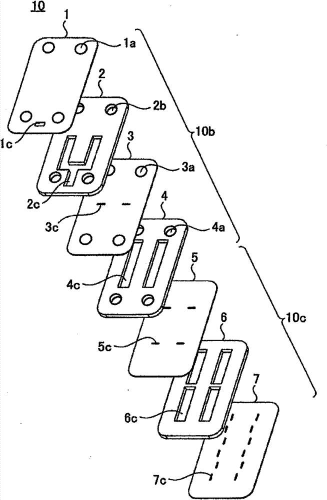
[0031] figure 1 It is a perspective view showing Embodiment 1 of the laminated piping assembly of the present invention. figure 2 yes figure 1 An exploded perspective view of the stacked tubing assembly of . The laminated pipe assembly 100 has: a waveguide pipe part (pipe part) 10; a control substrate 20 as a connected part connected to the waveguide pipe part 10 by self-tapping screws 40; High frequency device 30 on 20. The high-frequency device 30 has a function of transmitting and receiving microwaves or millimeter waves. The waveguide piping component 10 is formed by stacking a plurality of sheet-like components and integrating them by surface bonding. The waveguide pipe component 10 has a hollow pipe (waveguide) not shown formed in the inner layer. Bottom holes 10a for screws are formed on the waveguide pipeline part 10. On the other hand, a through hole 20a is formed on the control substrate 20, and the control substrate 20 is driven into the waveguide pipeline by ...

Embodiment approach 2

[0041] The structure of the laminated piping assembly of the present embodiment is roughly the same as that of the first embodiment. When the material of the waveguide pipeline part 10 is stainless steel, it is generally difficult to connect with self-tapping screws due to its high hardness (Vickers hardness is 250Hv or more) (it can be done with general self-tapping screws). The approximate standard of the hardness of the material to be connected is less than 50% of the screw hardness, 220Hv or less).

[0042] Therefore, in the present embodiment, the entire waveguide line component 10 or the chip component 2 forming the bottom hole 2b is annealed at about 800° C. (heat treatment step). Thereby, the hardness is reduced to 220Hv or less, and a structure capable of screwing can be realized even for stainless steel components.

[0043] In addition, regarding the above-mentioned heat treatment, when a bonding method by high-temperature heating typified by diffusion bonding is us...


PUM


Abstract

A stacked conduit assembly comprises: a conduit part 10 in which a plurality of plate-like parts 1 to 7 are stacked and integrated, and a hollow conduit is formed in an inner layer; and a control board 20 to be fastened to the conduit part 10 by a screw. The plate-like parts includes a plurality of plate-like parts that respectively form a side wall, an upper face, and a bottom face of the conduit, a pilot hole 2b is formed in a plate-like part 2 that forms the side wall of the conduit, and the screw is a tapping screw 40 that taps by itself in the pilot hole and is fastened. Thus, a stacked conduit assembly that can stabilize a screw engagement state and realize downsizing (thinning) of devices and cost reduction can be obtained.

Description

technical field [0001] The present invention relates to a laminated piping assembly in which a plurality of sheet-shaped parts are laminated and integrated, and a piping part forming a hollow piping is connected to a connected part such as a control board. In addition, it relates to a screw connection method of piping parts in which a connected part is connected to the piping parts with screws. Background technique [0002] In the waveguide path parts or waveguide structure antennas used in microwave or millimeter wave radar or communication equipment, it is required to have a complex multi-layer structure of hollow pipelines, especially for civilian equipment such as vehicle radar, which must be done to miniaturization and high productivity. For this reason, as a form of piping parts in which a hollow waveguide (pipe) is formed, a plurality of sheet-shaped parts formed with punched holes of various shapes are laminated and integrated by methods such as surface bonding. Co...

Claims


Application Information

Patent Timeline
Patent Type & Authority Patents(China)
IPC IPC(8): F16B5/02H01P11/00
CPCF16B5/02H01P1/20345F16B2001/0064H01P11/007Y10T29/49963Y10T137/86686F16B2200/93
Inventor 桥本实羽生诚志
Owner MITSUBISHI ELECTRIC CORP
Why Eureka
Try Eureka