Membrane electrode assembly and fuel cell

A membrane-electrode assembly and cathode technology, applied in fuel cells, solid electrolyte fuel cells, fuel cell components, etc., can solve problems such as damage to gas diffusivity, and achieve the effect of improving gas diffusivity and increasing battery voltage

Active Publication Date: 2013-04-03
SANYO ELECTRIC CO LTD
View PDF1 Cites 0 Cited by
  • Summary
  • Abstract
  • Description
  • Claims
  • Application Information

AI Technical Summary

Problems solved by technology

However, if the moisture retention property is improved, water clogging will easily occur and the gas diffusibility will be impaired.

Method used


Image

  • Membrane electrode assembly and fuel cell
  • Membrane electrode assembly and fuel cell
  • Membrane electrode assembly and fuel cell

Examples


Embodiment approach

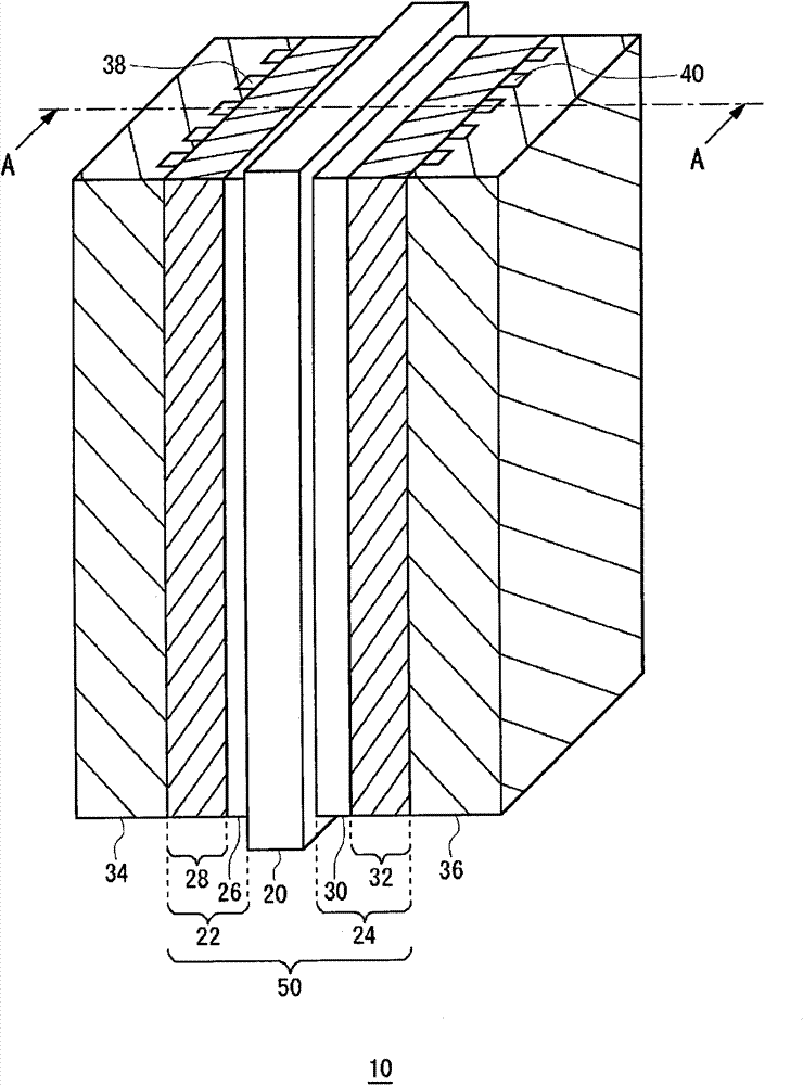
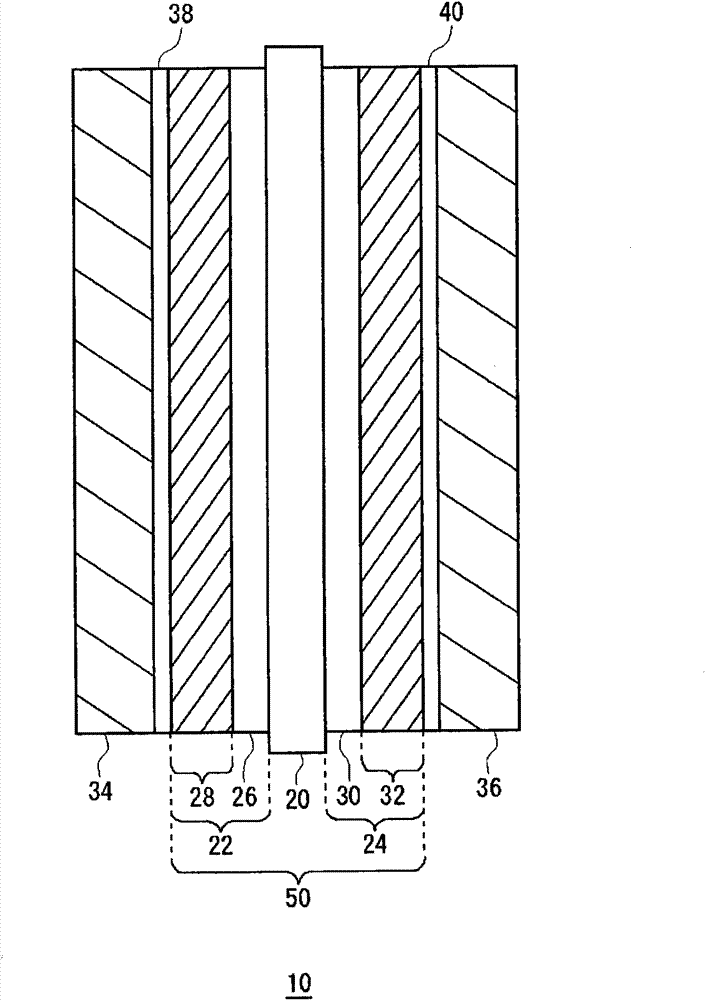
[0030] figure 1 It is a perspective view schematically showing the structure of the fuel cell 10 of the embodiment. figure 2 Yes figure 1 Sectional view on line A-A of . The fuel cell 10 includes a flat membrane electrode assembly 50 , and a separator 34 and a separator 36 are provided on both sides of the membrane electrode assembly 50 . In this example, only one membrane electrode assembly 50 is shown, but a plurality of membrane electrode assemblies 50 may be stacked via spacers 34 and 36 to form a fuel cell stack. Membrane electrode assembly 50 has solid polymer electrolyte membrane 20 , anode 22 and cathode 24 .

[0031] The anode 22 has a laminated body composed of a catalyst layer 26 and a gas diffusion layer 28 . On the other hand, cathode 24 has a laminated body composed of catalyst layer 30 and gas diffusion layer 32 . The catalyst layer 26 of the anode 22 and the catalyst layer 30 of the cathode 24 are provided facing each other with the solid polymer electrol...


PUM

PropertyMeasurementUnit
thicknessaaaaaaaaaa
thicknessaaaaaaaaaa

Abstract

A membrane electrode assembly includes an solid polymer electrolyte membrane, an anode, and a cathode. The cathode has a stacked body of a catalyst layer and a gas diffusion layer. The catalyst layer has platinum-cobalt-supporting carbon particles and an ion conductor. The ratio (P2 / P1) of the pore volume P2 (ml / g) per gram of catalyst layer in a second micro-pore diameter, ranging from 0.1 µm to less than 1 µm, over the pore volume P1 per gram of catalyst layer in a first micro-pore diameter, ranging from 0.01 µm to less than 0.1 µm, is in a range of 3.8 to 8.3.

Description

technical field [0001] The present invention relates to fuel cells that generate electricity through the electrochemical reaction of hydrogen and oxygen. Background technique [0002] In recent years, fuel cells that have high energy conversion efficiency and do not generate harmful substances through power generation reactions have attracted attention. As one of such fuel cells, a solid polymer fuel cell operating at a low temperature of 100° C. or lower is known. [0003] A solid polymer fuel cell has a basic structure in which a solid polymer membrane as an electrolyte membrane is disposed between a fuel electrode and an air electrode, and a hydrogen-containing fuel gas is supplied to the fuel electrode, and an oxygen-containing oxidant gas is supplied to the air electrode. A device that generates electricity by following an electrochemical reaction. [0004] Fuel electrode: H 2 →2H + +2e - …(1) [0005] Air electrode: 1 / 2O 2 +2H + +2e - →H 2 O...(2) ...

Claims


Application Information

Patent Timeline
Patent Type & Authority Patents(China)
IPC IPC(8): H01M4/86H01M8/02H01M8/10
CPCY02E60/521H01M4/8605H01M4/8652H01M4/925H01M8/1004Y02E60/50
Inventor 松冈孝司
Owner SANYO ELECTRIC CO LTD
Why Eureka
Try Eureka