Wind power generation hydraulic system

A technology of hydraulic system and solenoid valve, applied in wind power generation, wind turbine, wind turbine control, etc., can solve the problems of loss of pipeline pressure, excessive braking force, failure of main shaft braking device and yaw braking device to work properly, etc. , to achieve the effect of balanced flow speed and smooth movement

Inactive Publication Date: 2011-02-23
SHANGHAI ELECTRICAL HYDRAULICS & PNEUMATICS
View PDF4 Cites 12 Cited by
  • Summary
  • Abstract
  • Description
  • Claims
  • Application Information

AI Technical Summary

Problems solved by technology

[0003] When the main shaft brake unit and yaw brake unit are braking, the hydraulic system failure is often caused by the hydraulic oil pressure in the hydraulic system pipeline is too high, or the hydraulic oil flow rate of the hydraulic oil to the main shaft brake cylinder is uneven. resulting in excessive or insufficient braking force
[0004] When the oil pump fails, the motor needs to be shut down intermittently, or the oil pipeline is cut off, the hydraulic system failure will often be caused by the hydraulic oil pressure in the hydraulic system pipeline being too high, insufficient or unstable, affecting the main shaft brake device and yaw brake device In addition, during the maintenance process, the pressure in the pipeline is often reduced due to the loss of hydraulic oil in the hydraulic system, which makes the main shaft brake device and yaw brake device unable to work normally.

Method used


Image

  • Wind power generation hydraulic system
  • Wind power generation hydraulic system

Examples


Embodiment Construction

[0024] The present invention is further described below in conjunction with specific embodiment:

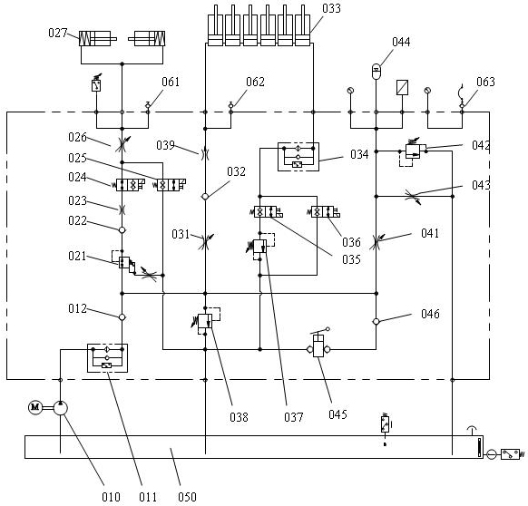
[0025] See figure 1 , which is a schematic diagram of the system of the present invention, including an oil pump 010 , a main shaft braking unit, a yaw braking unit, a safety pressure maintaining unit and an external fuel tank 050 .

[0026] The oil pump 010 is connected to the main shaft brake unit, the yaw brake unit and the safety pressure maintaining unit through the pipelines of the first filter 011 and the second one-way valve 012 through the same pipeline.

[0027] The spindle brake unit is composed of the oil pump 010 through the first filter 011, the second one-way valve 012, the pressure reducing valve 021, the third one-way valve 022, the throttle plug 023, the first electromagnetic valve 024, and the third adjustable flow valve. The valve 026 is connected with the pipeline of the spindle brake oil cylinder group 027.

[0028] Main shaft brake oil cylinder group 027 ...


PUM


Abstract

The invention discloses a wind power generation hydraulic system, which comprises an oil pump, an external oil tank, a spindle brake unit, yawing brake unit and a safe pressure maintaining unit, wherein the oil pump is connected with a spindle brake oil cylinder group through a reducing valve and a first electromagnetic valve, connected with a yawing brake oil cylinder group through a first adjustable throttle, and connected with an energy accumulator through a second adjustable throttle by the same pipeline; the spindle brake oil cylinder group is connected with the external oil tank through a pipeline; the yawing brake oil cylinder group is connected with the external oil tank through a third electromagnetic valve and a first overflow valve by a pipeline; the energy accumulator is connected with the external oil tank through a third overflow valve by a pipeline; and the external oil tank is connected with the yawing brake oil cylinder group through a second overflow valve and the first adjustable throttle by a pipeline. The wind power generation hydraulic system can perform spindle brake and yawing brake, and is provided with the system pressure maintaining device.

Description

technical field [0001] The invention belongs to the technical field of wind power generation, and in particular relates to a hydraulic system for wind power generation. Background technique [0002] The hydraulic brake of the wind turbine mainly includes the main shaft brake unit and the yaw brake unit. [0003] When the main shaft brake unit and yaw brake unit are braking, the hydraulic system failure is often caused by the hydraulic oil pressure in the hydraulic system pipeline is too high, or the hydraulic oil flow rate of the hydraulic oil to the main shaft brake cylinder is uneven. This results in excessive or insufficient braking force. [0004] When the oil pump fails, the motor needs to be shut down intermittently, or the oil pipeline is cut off, the hydraulic system failure will often be caused by the hydraulic oil pressure in the hydraulic system pipeline being too high, insufficient or unstable, affecting the main shaft brake device and yaw brake device In addit...

Claims


Application Information

Patent Timeline
Patent Type & Authority Applications(China)
IPC IPC(8): F03D7/00F15B11/02F15B1/02F15B21/04
CPCY02E10/723Y02E10/72
Inventor 陈琮诗时燕
Owner SHANGHAI ELECTRICAL HYDRAULICS & PNEUMATICS
Why Eureka
Try Eureka