Sinusoidal pressure generation chamber with filter characteristics
A filter characteristic, pressure chamber technology, applied in the measurement of fluid pressure, measuring devices, instruments, etc., can solve problems such as large distortion, affecting measurement and calibration accuracy, and deformation of the pressure wave shape of sinusoidal pressure chambers, to improve the degree of distortion and dynamic and static. Amplitude ratio, improving measurement characteristics and calibration range, and eliminating the effects of higher harmonics
- Summary
- Abstract
- Description
- Claims
- Application Information
AI Technical Summary
Problems solved by technology
Method used
Image

Examples
Embodiment Construction
[0023] The sinusoidal pressure generating cavity with filtering characteristics of the present invention will be further described below in conjunction with the accompanying drawings and specific embodiments.
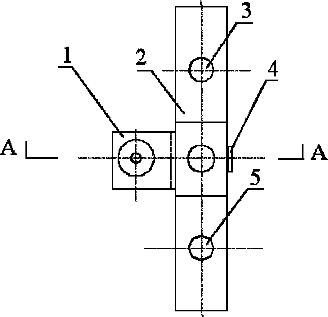
[0024] Such as figure 1 As shown, the sinusoidal pressure generating chamber with filtering characteristics in the present invention is mainly composed of a main and auxiliary structure sinusoidal pressure chamber 1, a mechanical filter 6, a sealing head 4, a chamber support 2 and other components.
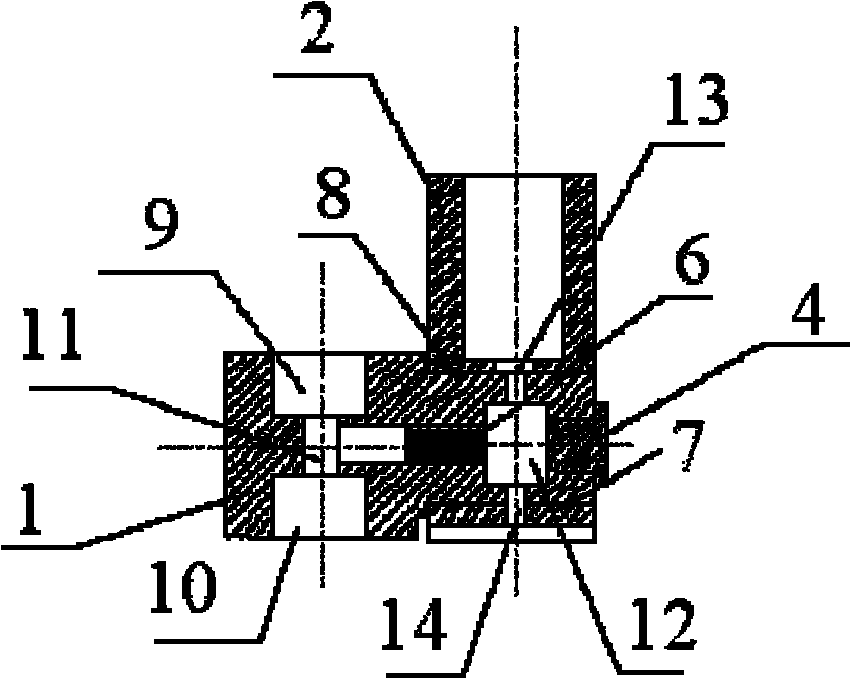
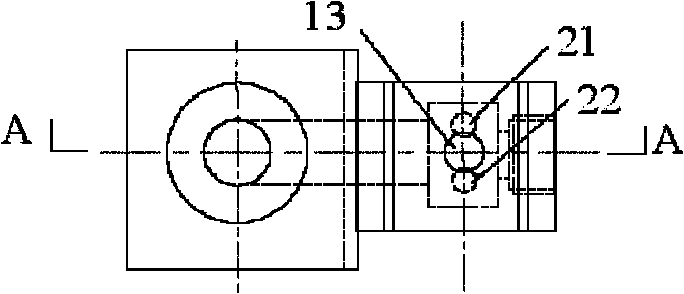
[0025] Such as Figure 2~4 As shown, the interior of the main and auxiliary structure sinusoidal pressure chamber 1 is hollow, one side is the auxiliary sinusoidal pressure chamber 11, and the other side is the main sinusoidal pressure chamber 12; There are mechanical filters6. The top and bottom of the auxiliary sinusoidal pressure chamber 11 are grooved respectively, forming a sensor installation position one 9 and a sensor installation position two 10 . The top and bo...
PUM
 Abstract
Description
Claims
Application Information
 - R&D
- Intellectual Property
- Life Sciences
- Materials
- Tech Scout
- Unparalleled Data Quality
- Higher Quality Content
- 60% Fewer Hallucinations
Browse by: Latest US Patents, China's latest patents, Technical Efficacy Thesaurus, Application Domain, Technology Topic, Popular Technical Reports.
© 2025 PatSnap. All rights reserved.Legal|Privacy policy|Modern Slavery Act Transparency Statement|Sitemap|About US| Contact US: help@patsnap.com