
Automobile exhaust waste heat recycling and charging device based on pulse tube generator

A technology for vehicle exhaust and waste heat recovery, applied in electric vehicle charging technology, electric vehicles, exhaust devices, etc., can solve the problems of vehicle exhaust emission, difficult assembly, huge size, etc., to improve system reliability and process manufacturing. Feasibility, low machining difficulty

Active Publication Date: 2019-10-08
TONGJI UNIV
View PDF24 Cites 1 Cited by
  • Summary
  • Abstract
  • Description
  • Claims
  • Application Information

AI Technical Summary

Problems solved by technology

[0003] However, due to the low grade of waste heat from automobile exhaust and the particularity of the automobile itself, most of the current waste heat recovery devices for automobile exhaust are in the laboratory stage, with their own shortcomings, and it is difficult to put them into practical use: the thermal efficiency of semiconductor thermoelectric power generation is low, and the long-term operation is reliable Poor performance; Abandoned turbocharging has a huge impact on vehicle exhaust emissions; Rankine cycle has complex structure and huge size; Stirling generator requires high machining accuracy, difficult assembly, and complicated movement

Method used


Image

  • Automobile exhaust waste heat recycling and charging device based on pulse tube generator
  • Automobile exhaust waste heat recycling and charging device based on pulse tube generator
  • Automobile exhaust waste heat recycling and charging device based on pulse tube generator

Examples


Embodiment 1

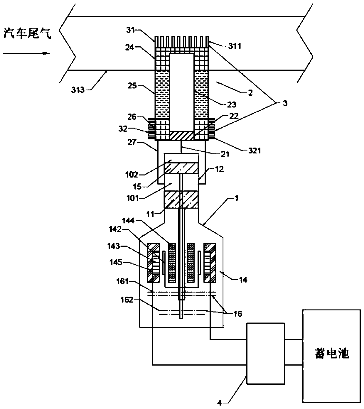
[0026] A charging device for recovering waste heat from automobile exhaust based on a pulse tube generator, such as figure 1 As shown, it includes a single expander 1 with work recovery capability, a heat head 2 of a pulse tube generator, a heat exchange system 3 and a rectification system 4 .

[0027] The expander expansion cavity 101 is formed between the expansion piston 11 and the work recovery piston 15 in the expander cylinder 12, and the expander work recovery cavity 102 is formed by the back cavity formed by the cylinder 12 and the work recovery piston 15;

[0028] The thermal head 2 of the pulse tube generator consists of a connecting pipe 21 at the room temperature end of the pulse tube, a gas homogenizer 22 at the room temperature end of the pulse tube, a pulse tube 23, a heat exchanger 24 at the high temperature end of the thermal head, a regenerator 25, and a heat exchanger at the room temperature end of the thermal head 26 and the connecting pipe 27 at the room t...

Embodiment 2

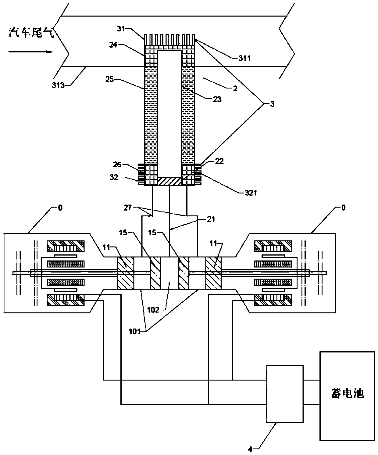
[0039] A car exhaust waste heat recovery charging device based on a pulse tube generator, the difference from Embodiment 1 is that the expansion machine 1 with work recovery capability is changed from one to two, and it is a double-headed symmetrical expansion machine 0, such as figure 2 As shown, two linear motors 14, two expansion pistons 11 and two work recovery pistons 15 are symmetrically arranged, and the two expanders face each other and share one expander cylinder 12. Two expander expansion chambers 101 are formed, and the work back chambers of the two work recovery pistons are connected to form an expander work recovery chamber 102 . The connecting pipe 27 at the room temperature end of the regenerator connects the expansion chambers 101 of the two expanders with the room temperature end of the regenerator, and the connecting pipe 21 at the room temperature end of the vessel connects the work recovery chamber 102 of the expander with the room temperature end of the ve...

Embodiment 3

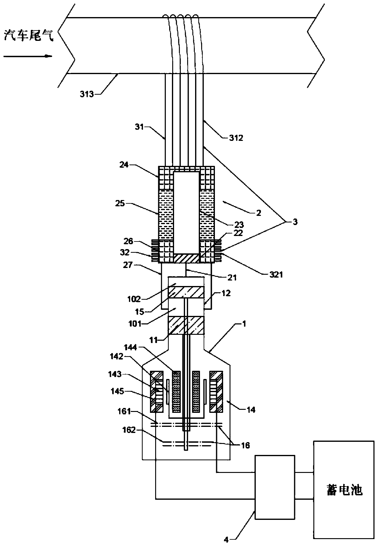
[0041] A charging device for recovering waste heat from automobile exhaust based on a pulse tube generator, such as image 3 As shown, the difference from Embodiment 1 is that the high-temperature end heat exchange system 31 uses one or more high-temperature heat pipes 312, and the evaporation section of the high-temperature heat pipes 312 is wound around the automobile exhaust main pipe 313, and is in thermal contact with the pipe wall. The condensing section of the heat pipe 312 is riveted with the high temperature heat exchanger 24 of the heat head, and the heat conduction between the high temperature heat exchanger 24 of the heat head and the exhaust gas of the automobile is completed through the phase conversion heat in the high temperature heat pipe 312 . The linear motor 14 adopted in this embodiment is a moving magnet type, including a magnet 142, a coil 143, an inner iron core 144, and an outer iron core 145; the magnet 142 and the expansion piston 11 move together, so...


PUM


Abstract

The invention relates to an automobile exhaust waste heat recycling and charging device based on a pulse tube generator. The device comprises an expansion machine (1) capable of recovering work, a pulse tube generator thermal head (2), a heat exchange system (3) and a rectifying system (4), wherein the heat exchange system (3) takes heat from high-temperature exhaust gas and then release heat at the room temperature end; through the simple harmonic motion of a piston of the expansion machine (1) capable of recovering work, the transmission of acoustical power from one high-temperature end to another high-temperature end and the recycling process of a working medium in the expansion machine (1) and the pulse tube generator thermal head (2) is completed, so that electricity power is generated by the piston motion of the expansion machine (1) to complete the process of electricity generation, thus being capable of charging automobile storage batteries though the rectifying system (4). Compared with the prior art, the automobile exhaust waste heat recycling and charging device based on the pulse tube generator has the advantages that thermal energy is recycled to provide power to an automobile while thermal pollution of the automobile is reduced, so that a positive circulation of energy saving and emission reduction inside the automobile is realized; in addition, no movement component is arranged at the high-temperance, no high-precision matching requirement is imposed, and the machining difficulty is low, thus being capable of improving reliability of a system and feasibilityof processing and manufacturing.

Description

technical field [0001] The invention relates to a waste heat power generation device, in particular to an automobile exhaust waste heat recovery charging device based on a pulse tube generator. Background technique [0002] The energy released by fuel combustion is converted into mechanical energy by the internal combustion engine, accounting for only about one-third of the total energy, and most of it is taken away by vehicle exhaust and released into the atmosphere. On the one hand, the emission of a large amount of greenhouse gases has caused environmental pollution, and on the other hand, a large amount of heat has been discharged without utilization, resulting in a waste of energy. If we can make full use of the waste heat of vehicles and convert part of it into electric energy or vehicle kinetic energy, it will not only improve energy utilization, reduce vehicle energy consumption, increase vehicle mileage, but also reduce oil consumption, reduce greenhouse gas emissio...

Claims


Application Information

Patent Timeline
IPC IPC(8): F01N5/02F25B27/02F25B40/06B60L53/00
CPCB60L53/00F01N5/025F25B27/02F25B40/06Y02T10/12Y02T10/70Y02T10/7072Y02T10/72Y02T90/14Y02A30/274
Inventor 朱绍伟许晟唐雨晴
Owner TONGJI UNIV
Learn More