Self-positioning detachable concrete durability test stress loading device
A technology of durability testing and stress loading, which is applied to measuring devices, using stable tension/pressure to test the strength and strength characteristics of materials, etc. Convenience, reduced stress relaxation, easy to grasp effect
- Summary
- Abstract
- Description
- Claims
- Application Information
AI Technical Summary
Problems solved by technology
Method used
Image

Examples
Embodiment Construction
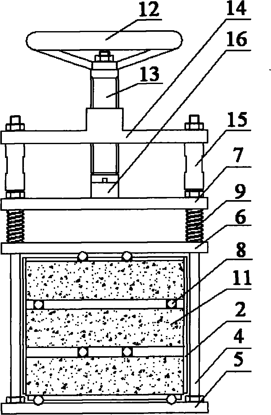
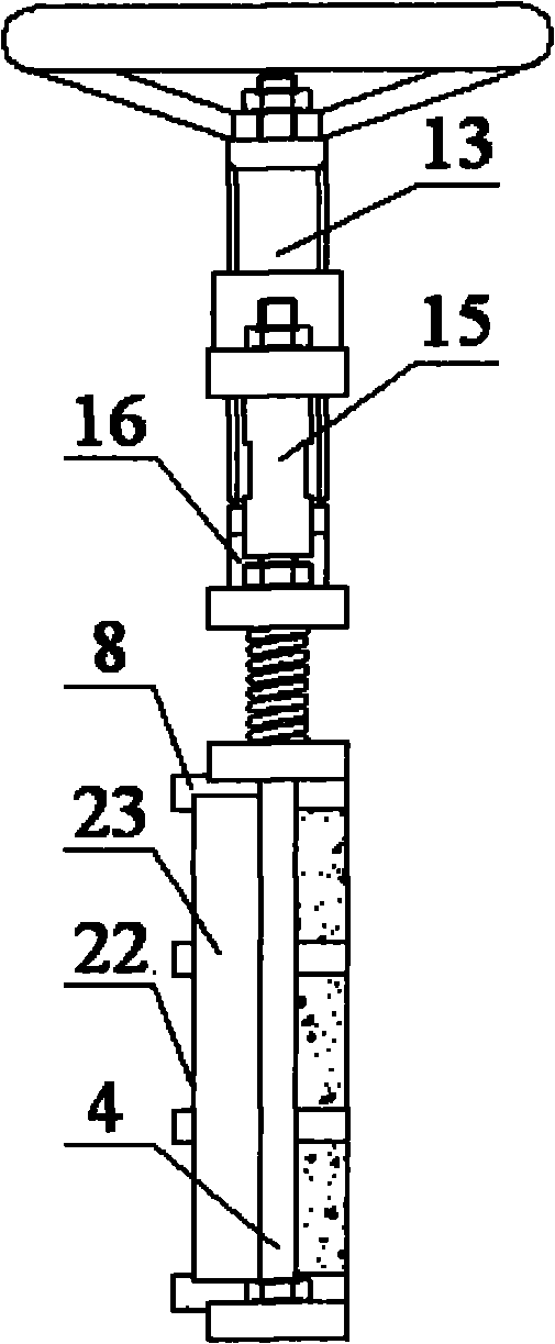
[0034] The self-positioning and detachable concrete durability test stress loading device of the present invention is composed of stress loading fixture 1, positioning fixture 2 and stress measurement and control fixture 3, which are used together to form a detachable structure with self-positioning function. Below in conjunction with accompanying drawing, connection mode and effect thereof of each part of the present invention are set forth as follows:
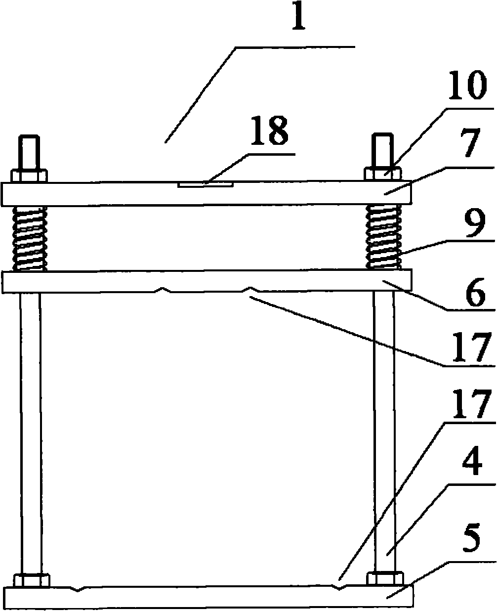
[0035] see Figure 1A and figure 2 As shown, the stress loading fixture 1 includes two uprights 4 , a lower pressing plate 5 , a middle pressing plate 6 , an upper pressing plate 7 , multiple rollers 8 and two springs 9 for applying constant stress to a concrete specimen 11 . Wherein, each column 4 lower end and the lower pressing plate 5 both sides are provided with supporting threads and screw holes, and the two are fixed with nuts 10 after being threaded; Pressing plate 6, spring 9 and upper pressing plate 7 pass through...
PUM
 Abstract
Description
Claims
Application Information
PatSnap Eureka turns technology decisions into work you can execute. Powered by our Innovation Knowledge Graph, it runs expert workflows across engineering, life sciences, materials and intellectual property. Get your review-ready output in minutes.


