Pressurizing common-rail oil injection system

A technology of fuel injection system and common rail, which is applied in the direction of charging system, fuel injection device, engine components, etc., can solve the problems of difficult control of fuel injection rate, low injection pressure, etc., so as to facilitate the design and layout, reduce emissions and energy Loss, effect of compactness

Inactive Publication Date: 2011-03-09
FAW GROUP
View PDF9 Cites 15 Cited by
  • Summary
  • Abstract
  • Description
  • Claims
  • Application Information

AI Technical Summary

Problems solved by technology

However, the fuel injection systems described in the above two patents cannot meet the requirement of lower injection pressure during pre-injection and post-injection, and it is also difficult to control the fuel injection rate in the ignition lag period.

Method used


Image

  • Pressurizing common-rail oil injection system
  • Pressurizing common-rail oil injection system
  • Pressurizing common-rail oil injection system

Examples


Embodiment Construction

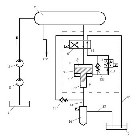
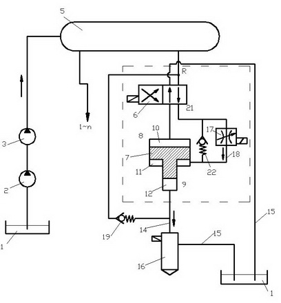
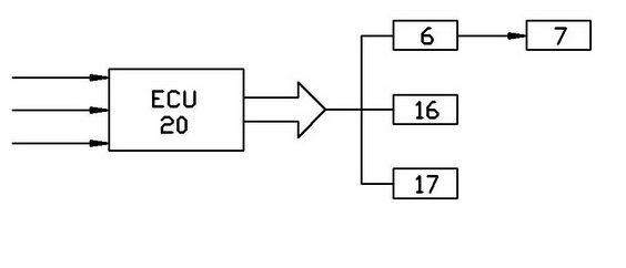
[0025] The present invention includes a high-pressure oil supply pump 3, a common rail pipe 5, a high-pressure oil pipe 14, and an oil return pipe 15, and is characterized in that it also includes a control valve 6, a booster valve 7, an electric control unit 20 and a plurality of electronically controlled fuel injectors 16, The booster valve 7 is installed behind the common rail pipe 5 and each control valve 6, and is connected to each other with a high-pressure oil pipe 14,

[0026] a. The control valve 6 is a two-position four-way high-speed electromagnetic reversing valve, which is supplied with fuel at the common rail pressure Pc by the common rail pipe 5, and can quickly supply fuel from the upper chamber 10 of the booster valve 7 Switch to supply oil to the lower chamber 11 of the booster valve 7, and the reversing action and reversing time of the control valve 6 are controlled by the above-mentioned electronic control unit 20;

[0027] b. The above-mentioned supercharg...


PUM


Abstract

The invention provides a pressurizing common-rail oil injection system, relating to an oil injection system of a diesel. The invention provides the pressurizing common-rail oil injection system with a pressurizing valve and a common-rail pipe arranged together. The system comprises a high-pressure oil supply pump, the common-rail pipe, a high-pressure oil pipe and an oil return pipe, and is characterized by further comprising a control valve, the pressurizing valve, an electric control unit and a plurality of electric control injectors, wherein the pressurizing valve is arranged behind the common-rail pipe and each control valve, and the pressurizing valve, the common-rail pipe and the control valves are connected by the high-pressure oil pipe one another. In the system, lower injection pressure is adopted in pre-injection and after-injection, the exhaust and energy consumption are reduced, stroke of a pressurizing plunger can be controlled, and unnecessary oil return loss can be reduced.

Description

technical field [0001] The invention relates to a fuel injection system for a diesel engine. Background technique [0002] In the existing common rail fuel injection system of diesel engines, it is an effective improvement method to further increase the injection pressure of the system by using a booster valve (also called a "pressure amplifier"). Chinese patent CN1158460C (WO0129409) discloses a technical solution for integrating a pressure amplifier and a fuel injector. The pressure amplifier is operated by the actuator through the control valve, and can amplify the primary pressure from 300 to 1000bar to 1600bar. The control valves used are a 2 / 2-way valve and a second valve. The disadvantage of the above-mentioned patent is that since the pressure amplifier is arranged in the fuel injector, the ratio of the outer diameter and cross-sectional area of ​​the booster plunger in the amplifier is limited by the diameter of the fuel injector, so it is difficult to meet the re...

Claims


Application Information

Patent Timeline
Patent Type & Authority Applications(China)
IPC IPC(8): F02M47/02F02M63/00F02M51/06
Inventor 李骏胡林峰戈非黄见
Owner FAW GROUP
Why Eureka
Try Eureka