Elastoplastic device for expansion joints in buildings and road engineering

A technology of road engineering and expansion joints, which is applied in the direction of buildings, roads, roads, etc., can solve the problems of poor sealing of installation holes, corrosion of plate steel bars, and short service life, and achieve favorable vibration reduction, smooth and seamless surfaces, and convenient construction quick effect

Inactive Publication Date: 2011-03-16
西安达盛隔震技术有限公司
View PDF5 Cites 20 Cited by
  • Summary
  • Abstract
  • Description
  • Claims
  • Application Information

AI Technical Summary

Problems solved by technology

When the expansion joint is hot, the filling will be extruded, but when it is cold shrinking, the extruded filling cannot be restored, and the water resistance will be damaged due to sand and gravel debris occupying the gap, and at the same time, it will cause corrosion of the steel reinforcement of the plate. short lifespan
[0008] 3. Geotextile expansion joint, geotextile expansion joint is an improved type of U-shaped zinc iron sheet expansion joint, which has the advantages of economy, construction simplicity and driving comfort, etc. It is theoretically superior to other types of expansion joints, but the aging performance poor
[0009] 4. Plate rubber expansion joints, due to the density and shock absorption of rubber materials, make their waterproof performance and noise reduction performance better, but due to the poor sealing of the installation holes, water leakage is caused. At the same time, due to the installation of expansion joints Defects, making the expansion joints jump out of the road after a period of use, causing bumps in driving

Method used


Image

  • Elastoplastic device for expansion joints in buildings and road engineering
  • Elastoplastic device for expansion joints in buildings and road engineering

Examples


Embodiment Construction

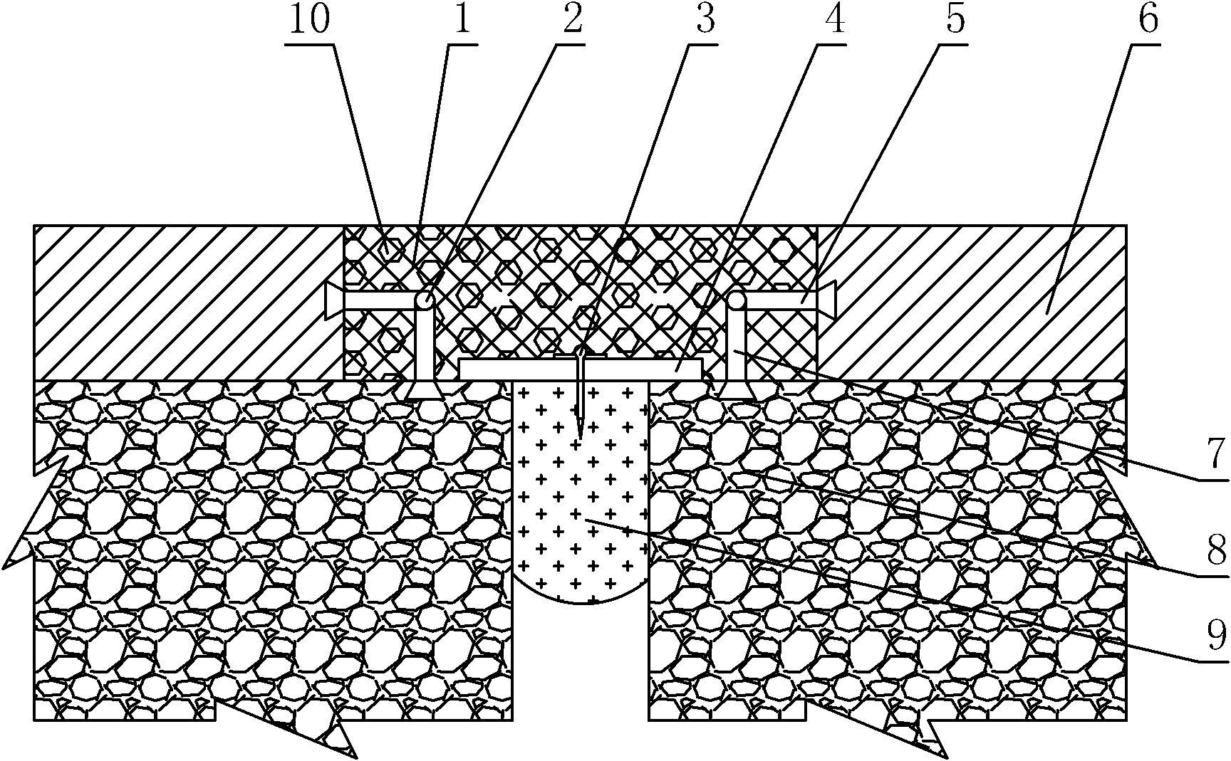
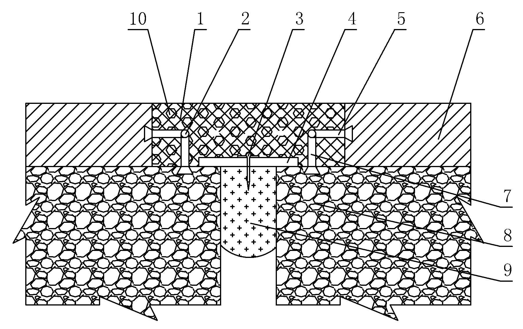
[0029] like figure 1 A kind of construction, road engineering expansion joint shown elastic-plastic body device comprises cast-in-place concrete layer 8 and the bituminous concrete pavement layer 6 that is arranged on the upper end of cast-in-place concrete layer 8, and the center of described cast-in-place concrete layer 8 is provided with Expansion joint, the inside of the expansion joint is filled with sponge body or foam body 9, the center of the asphalt concrete pavement layer 6 is provided with a notch, and the notch is filled with stretchable elastic body 1 and gravel 10, and the gravel 10 is evenly distributed in the stretchable elastic body 1, and a cover plate 4 is also arranged in the notch, and the cover plate 4 is located at the upper end of the expansion joint, and the cover plate 4 is fixedly connected with the sponge body or the foam body 9; Lower expansion bolts 7 are symmetrically arranged on the upper part of the cast-in-place concrete layer 8, and side expa...


PUM

PropertyMeasurementUnit
flexibilityaaaaaaaaaa

Abstract

The invention discloses an elastoplastic device for expansion joints in buildings and road engineering. The elastoplastic device comprises a cast-in-place concrete layer and a bituminous concrete pavement layer arranged on the upper end of the cast-in-place concrete layer, wherein the center of the cast-in-place concrete layer is provided with an expansion joint filled with sponges or foams; the center of the bituminous concrete pavement layer is provided with a notch which is filled with expansion elastomers and broken stones and is internally provided with a cover plate; lower expansion bolts are symmetrically arranged around the upper part of the cast-in-place concrete layer; lateral expansion bolts are symmetrically arranged around the inner side of the bituminous concrete pavement layer; and steel bars are arranged between the end parts of the lateral expansion bolts and the lower expansion bolts. The device disclosed by the invention has the advantages of simple structure and reasonable design, and is convenient and rapid in construction; the performance requirements of the expansion joints can be met, special expansion members are not needed to be arranged, and the problem of short service life of other expansion devices under small stroke can be effectively solved; and the device disclosed by the invention has the characteristics of good elasticity and neat and beautiful appearance, and can bear vehicle load.

Description

technical field [0001] The invention belongs to the technical field of construction and road expansion joints, and in particular relates to an elastic-plastic body device for construction and road engineering expansion joints. Background technique [0002] Expansion joint is one of the commonly used terms in construction engineering. Its main function is to prevent cracks in the house due to climate change. The usual practice is to reserve gaps at certain distances along the length of the building to disconnect the building from the roof, walls or floors and other components above the ground. The foundation of the building is less affected by temperature changes because it is buried underground. , does not have to be disconnected. For different structural systems, the distance between expansion joints is different, and there are special regulations on this in the current code "Code for Design of Concrete Structures" in my country. [0003] Expansion joints are a constructi...

Claims


Application Information

Patent Timeline
Patent Type & Authority Applications(China)
IPC IPC(8): E04B1/684E01C11/02E01C11/10E02D29/16E01D19/06
Inventor 王莫莲张春恒盛明勇
Owner 西安达盛隔震技术有限公司
Why Eureka
Try Eureka