Ladle slag roughing vibration detection device and method

A vibration detection and vibration signal technology, applied in the configuration of indicating equipment/measuring equipment, manufacturing tools, casting equipment, etc., can solve the problems of high rigidity of the operating arm, the impact of the large turntable, and the heavy weight, and achieve considerable economic benefits. , the effect of increasing the signal-to-noise ratio and increasing the signal energy

Inactive Publication Date: 2011-03-23
HUNAN RAMON SCI & TECH
View PDF1 Cites 7 Cited by
  • Summary
  • Abstract
  • Description
  • Claims
  • Application Information

AI Technical Summary

Problems solved by technology

And the process of enlarging the bale has an impact on the entire bale turret
This impact also causes a vibration shock to the manipulator arm
[0013] 3. During the detection process of ladle slag, the operator moves frequently on the slide plate, and each movement will affect the vibration of the operating arm and last for a period of time. If the slag is being dropped at this time, the useful signal will be buried and affect the next Slag judgment
[0014] 4. The on-site operating arm has high rigidity, heavy weight, and is fixed on the tundish car. When the vibration caused by the steel flow at the shroud is transmitted to the sensor on the operating arm, certain attenuation will occur
[0015] 5. In the continuous casting workshop, there are also some environmental vibrations, artificial vibrations and noises, such as the noise during electric arc furnace smelting, the vibration of the steel frame in the continuous casting workshop, and the walking vibration of people on the tundish platform. The extraction of useful signals has an impact on
Time domain analysis, frequency domain analysis, ceps frequency domain analysis, statistical analysis, wavelet analysis, etc. are performed on such signals, and judged by the neural network, the rate of false positives and false negatives is very high

Method used


Image

  • Ladle slag roughing vibration detection device and method
  • Ladle slag roughing vibration detection device and method
  • Ladle slag roughing vibration detection device and method

Examples


Embodiment Construction

[0040] The embodiments of the present invention will be described in detail below with reference to the accompanying drawings, but the present invention can be implemented in many different ways defined and covered by the claims. The same components are denoted by the same reference numerals in the drawings.

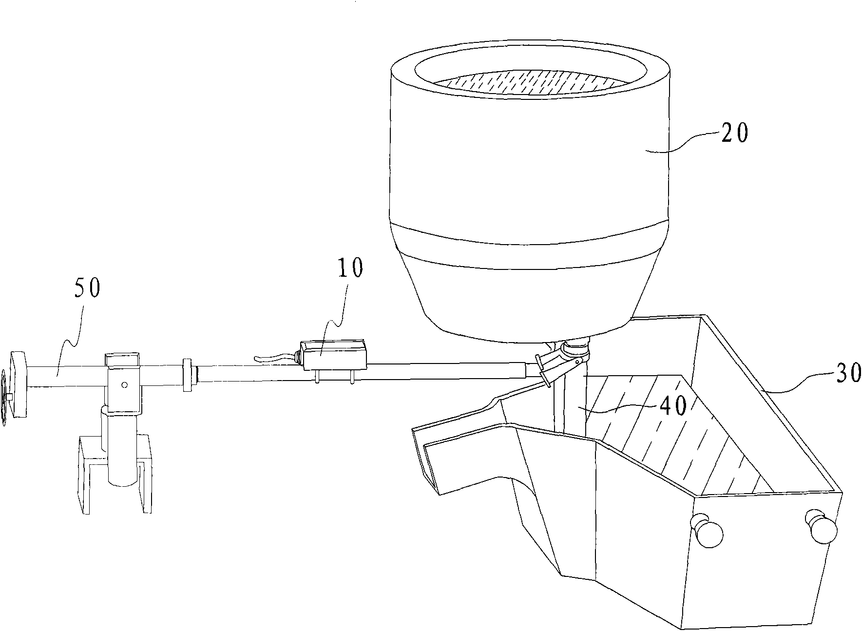
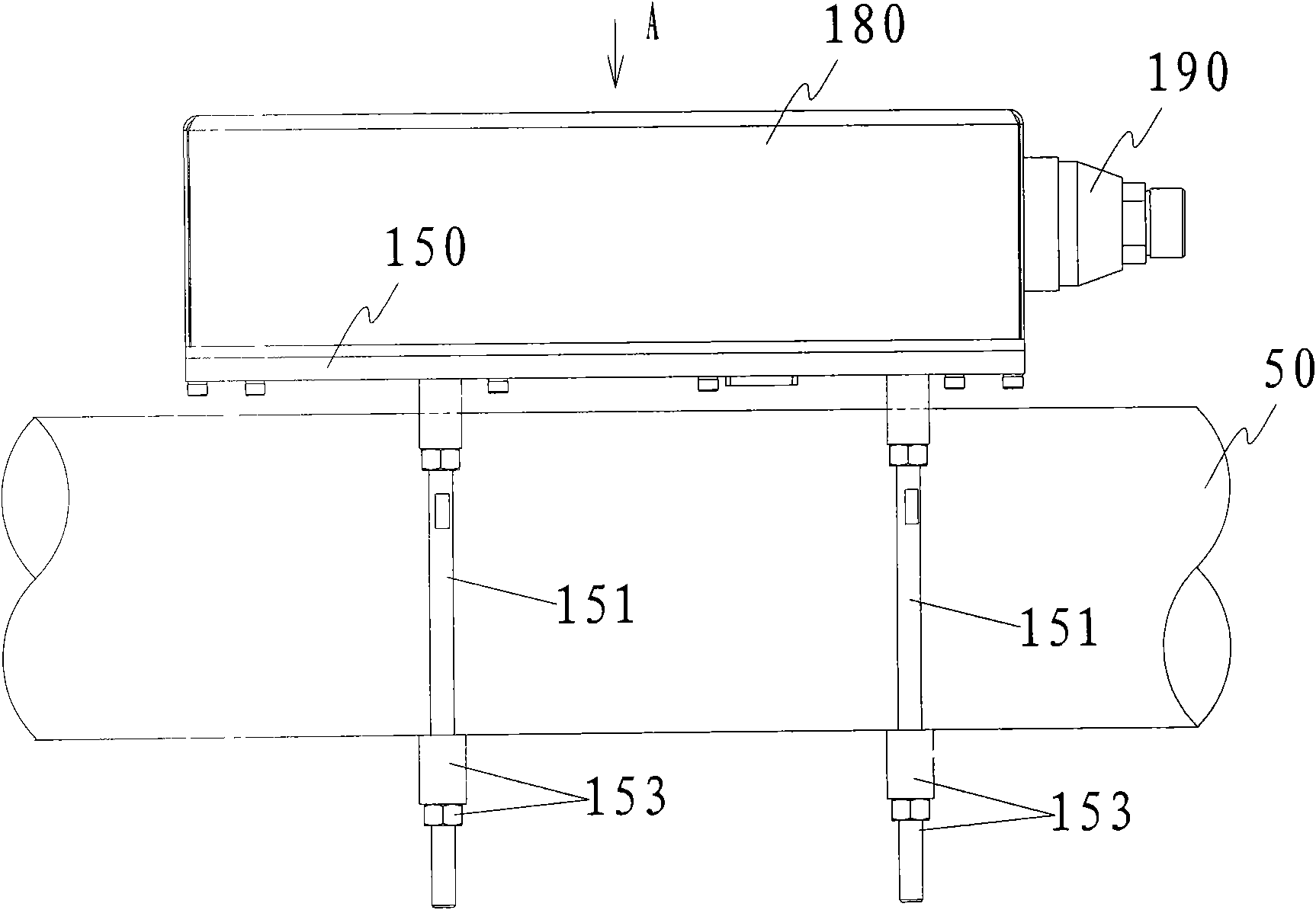
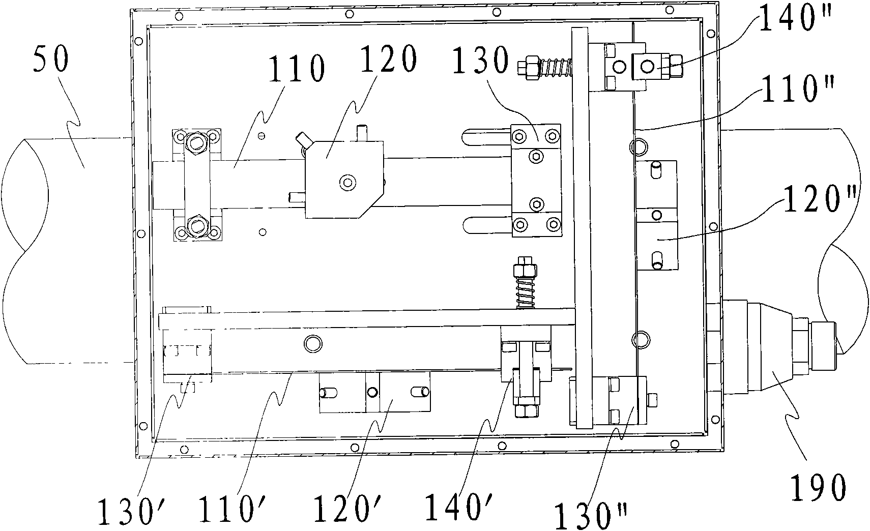
[0041]figure 1 A schematic diagram showing the application of the ladle slag vibration detection device according to the present invention to the ladle slag prediction, figure 2 It shows a schematic diagram of a ladle slag vibration detection device fixed to an operating arm according to a preferred embodiment of the present invention. Such as figure 1 and figure 2 As shown, in the continuous casting process, molten steel flows into the tundish 30 from the ladle 20 through the shroud 40, and the shroud 40 is inserted into the tundish 30, and the operating arm 50 of the steel plant is connected to the shroud 10 of the ladle 20. A vibration detection device 10 is inst...


PUM


Abstract

The invention discloses a ladle slag roughing vibration detection device which comprises a box body, at least one vibration shrapnel and at least one sensor, wherein the box body is fixed on an operating arm; the at least one vibration shrapnel is arranged in the box body along multiple directions, and one end of the vibration shrapnel is fixed on the box body or the baffle plate of the box body through a pressing plate; and the at least one sensor is respectively fixed on the vibration shrapnel and is used for detecting the vibration of each vibration shrapnel. The invention also discloses aladle slag roughing vibration detection method which comprises the following steps: arranging the vibration shrapnel for amplifying vibration signals on the operating arm, detecting the vibration signals of the vibration shrapnel by utilizing the sensor, and converting the vibration signals into electric signals; processing the electric signals to form sampling signals; and analyzing the samplingsignals in real time by utilizing a processor to send information of whether to rough slag or not. According to the ladle slag roughing vibration detection device and method provided by the invention, as long as weak vibration signals are detected, the free end of the shrapnel can vibrate to perform the amplifying effect on the signals, so that the sensor acquires the signals with stronger amplitude.

Description

technical field [0001] The invention relates to the field of metallurgical industry, in particular to a ladle slag vibration detection device and method applied to molten steel continuous casting equipment. Background technique [0002] In the continuous casting process, molten steel flows from the ladle into the tundish, and then enters the crystallizer through the tundish outlet, and solidifies into billets of various cross-sections after cooling. The slag layer has the effect of heat preservation and anti-oxidation on the molten steel in the ladle and the tundish. However, if the slag layer in the tundish is too thick, it will cause contamination of the molten steel, increase the erosion of the tundish refractory material and increase the thickness of the residual slag layer in the tundish. Therefore, controlling the amount of steel slag in the ladle is of great significance to improving the quality of the slab and increasing the continuous casting batch. [0003] At pre...

Claims


Application Information

Patent Timeline
Patent Type & Authority Applications(China)
IPC IPC(8): B22D11/18B22D11/114B22D2/00
Inventor 田陆曹令亚李向前
Owner HUNAN RAMON SCI & TECH
Why Eureka
Try Eureka