Electric furnace waste heat recycling and dedusting device

A technology of waste heat recovery and dust removal device, applied in furnaces, waste heat treatment, furnace components, etc., can solve the problems of complicated flue gas cooling and cooling system, increasing flue gas water content, and easy hardening of dust removal bags, so as to avoid equipment blockage and low temperature. Corrosion of sulfur dioxide, reduction of energy consumption for system operation, and reduction of ash discharge operating points

Inactive Publication Date: 2011-03-30
无锡市曜通环保机械有限公司
View PDF0 Cites 5 Cited by
  • Summary
  • Abstract
  • Description
  • Claims
  • Application Information

AI Technical Summary

Problems solved by technology

The above cooling methods all have certain disadvantages. The mechanical cooler is air-cooled, and the cooling effect is poor. The temperature of the inlet flue gas should not exceed 500°C, the cooling is limited, it is easy to block ash, and requires frequent maintenance; spray cooling is easy to increase the water content in the flue gas , not only makes the dust bag easy to harden, but also easily causes the bag to fail due to hydrolysis
[0004] Based on the above shortcomings, most of the above cooling methods are used in combination in the project, resulting in complex flue gas cooling system, huge equipment, heavy operation and maintenance workload, high resistance of the whole device, between 5500-8000Pa, and large energy consumption of the main fan
At the same time, the above-mentioned cooling methods are only pure cooling, resulting in the failure to fully utilize the sensible heat of high-temperature combustible gas, and a large amount of heat energy is wasted

Method used


Image

  • Electric furnace waste heat recycling and dedusting device
  • Electric furnace waste heat recycling and dedusting device
  • Electric furnace waste heat recycling and dedusting device

Examples


Embodiment Construction

[0012] The present invention will be further described below in conjunction with the accompanying drawings.

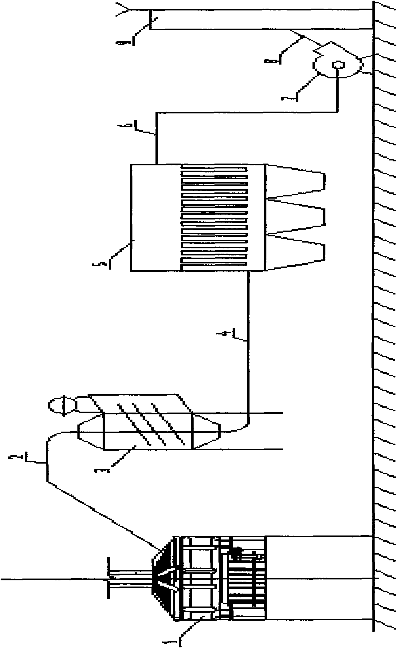
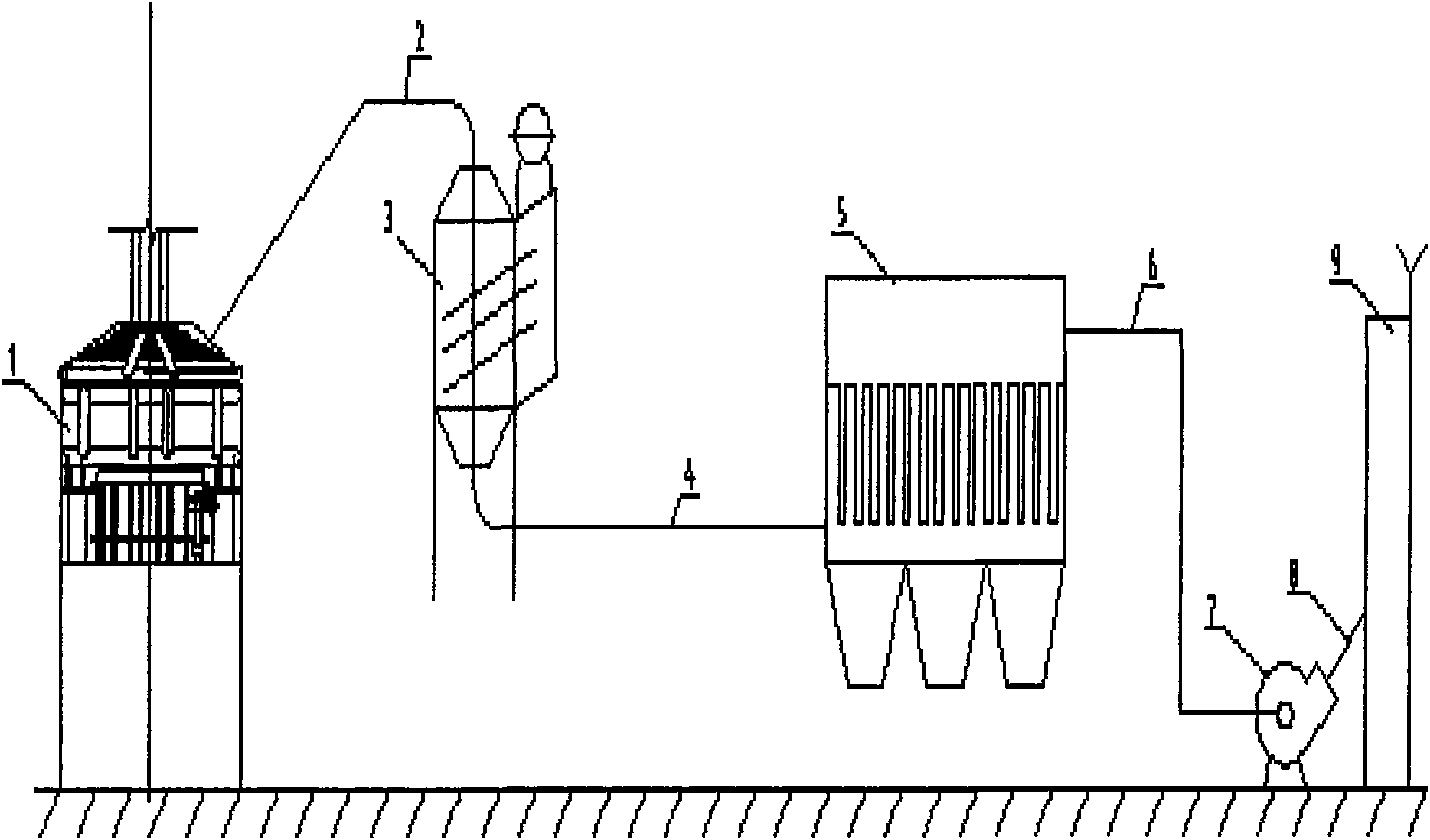
[0013] The present invention comprises the deduster 5, main blower 7, gas generating device 9 that are connected in sequence, and it also comprises heat pipe steam generator 3, and described heat pipe steam generator connects fully enclosed electric furnace 1 through gas pipeline (1) 2, and described heat pipe The output end of the steam generator is connected to the dust collector 5 through the pipe (2) 4 . The outlet connection pipe (3) 6 of the dust collector sends the purified combustible gas to the power generation device 9 . The heat pipe steam generator is composed of heat exchange tube bundles. The heat receiving section of the heat exchange tube bundle is placed in the high temperature flue, the flue gas traverses the heat pipe heating section, and the heat release section of the heat pipe element is inserted in the water-steam system.

[0014] The dust colle...


PUM


Abstract

The invention relates to an electric furnace waste heat recycling and dedusting device which comprises a deduster, a main fan, an exhaust cylinder and a heat pipe steam generator that are sequentially connected. The electric furnace waste heat recycling and dedusting device is characterized in that the heat pipe steam generator is connected with a fully-closed electric furnace through an insulation flue, and the output end of the heat pipe steam generator is connected with the deduster. The electric furnace waste heat recycling and dedusting device is further characterized in that the heat pipe steam generator is formed by combining a heat exchange pipe bundle, the heated section of the heat exchange pipe bundle is arranged in a high-temperature flue, the smoke transversely passes through the heat pipe heated section, and the heating section of a heat pipe element is inserted into a water-steam system. In the structure, the heat pipe steam generator is replaced with an equipment combination of a power cooler, a spraying cooler and the like, thus the system configuration is simplified, the smoke waste heat is recycled furthest, the cooling range is large and the operation cost is lowered.

Description

technical field [0001] The invention relates to an electric furnace waste heat recovery and dust removal device. Background technique [0002] In the prior art, the high-temperature combustible gas purification device of a fully enclosed electric furnace is a high-temperature combustible gas generating device, a cooling facility, and a dust collector connected in sequence through pipelines. [0003] At present, the commonly used cooling methods are: mechanical cooler air cooling, spray cooling, etc. The above cooling methods all have certain disadvantages. The mechanical cooler is air-cooled, and the cooling effect is poor. The temperature of the inlet flue gas should not exceed 500°C, the cooling is limited, it is easy to block ash, and requires frequent maintenance; spray cooling is easy to increase the water content in the flue gas , not only makes the dust bag easy to harden, but also easily causes the bag to fail due to hydrolysis. [0004] Based on the above shortcom...

Claims


Application Information

Patent Timeline
Patent Type & Authority Applications(China)
IPC IPC(8): F27D17/00F22B1/18F23J15/02B01D46/02
CPCY02P10/25
Inventor 顾云红
Owner 无锡市曜通环保机械有限公司
Why Eureka
Try Eureka