
Optical switchgear

A switch and light wave technology, applied in the field of optical communication, can solve the problems such as the inability to realize the light wave wavelength selective switch and the complex structure of the optical switch, and achieve the effect of simplifying the arrangement of the optical paths and reducing the production cost.

Inactive Publication Date: 2011-03-30
BEIJING ZHONGJING SYBO TECH
View PDF0 Cites 1 Cited by
  • Summary
  • Abstract
  • Description
  • Claims
  • Application Information

AI Technical Summary

Problems solved by technology

[0003] The purpose of the present invention is to provide a new type of optical switch selection structure in order to solve the complex structure of the existing optical switch and the inability to realize the function of the optical wavelength selective switch

Method used


Image

  • Optical switchgear
  • Optical switchgear
  • Optical switchgear

Examples


Embodiment Construction

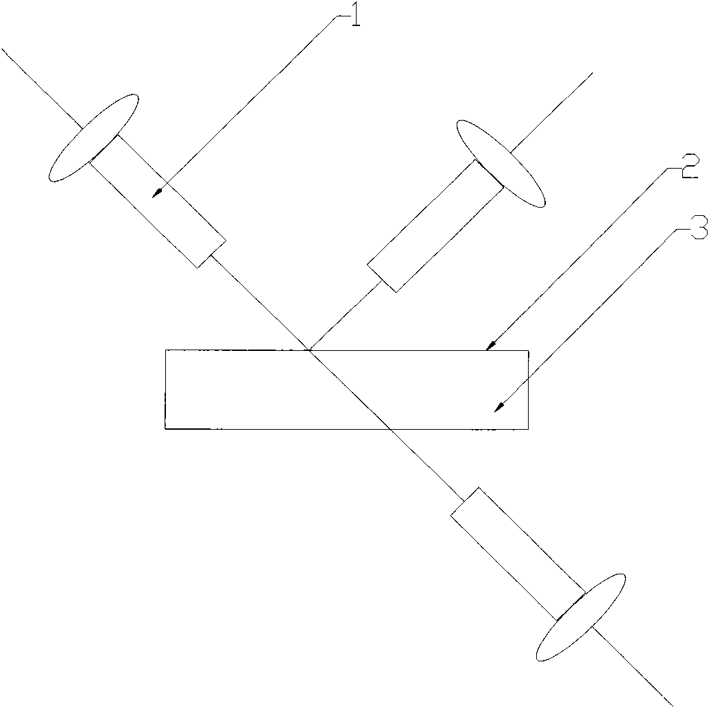
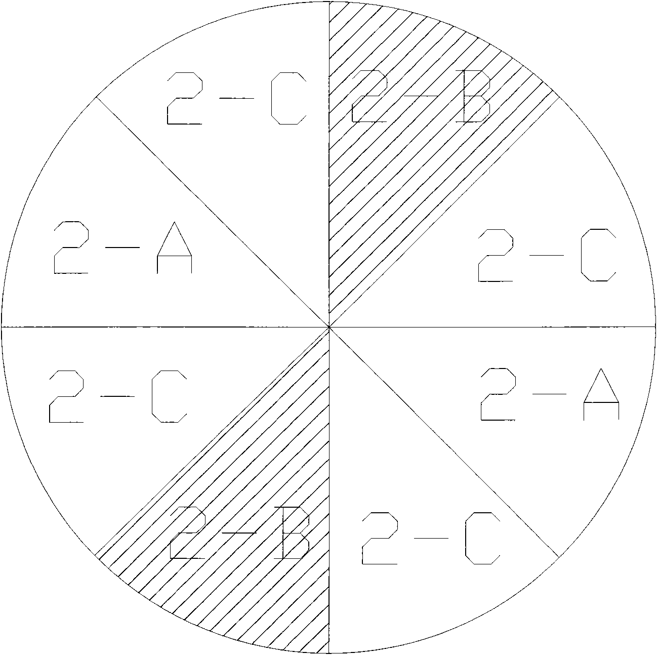
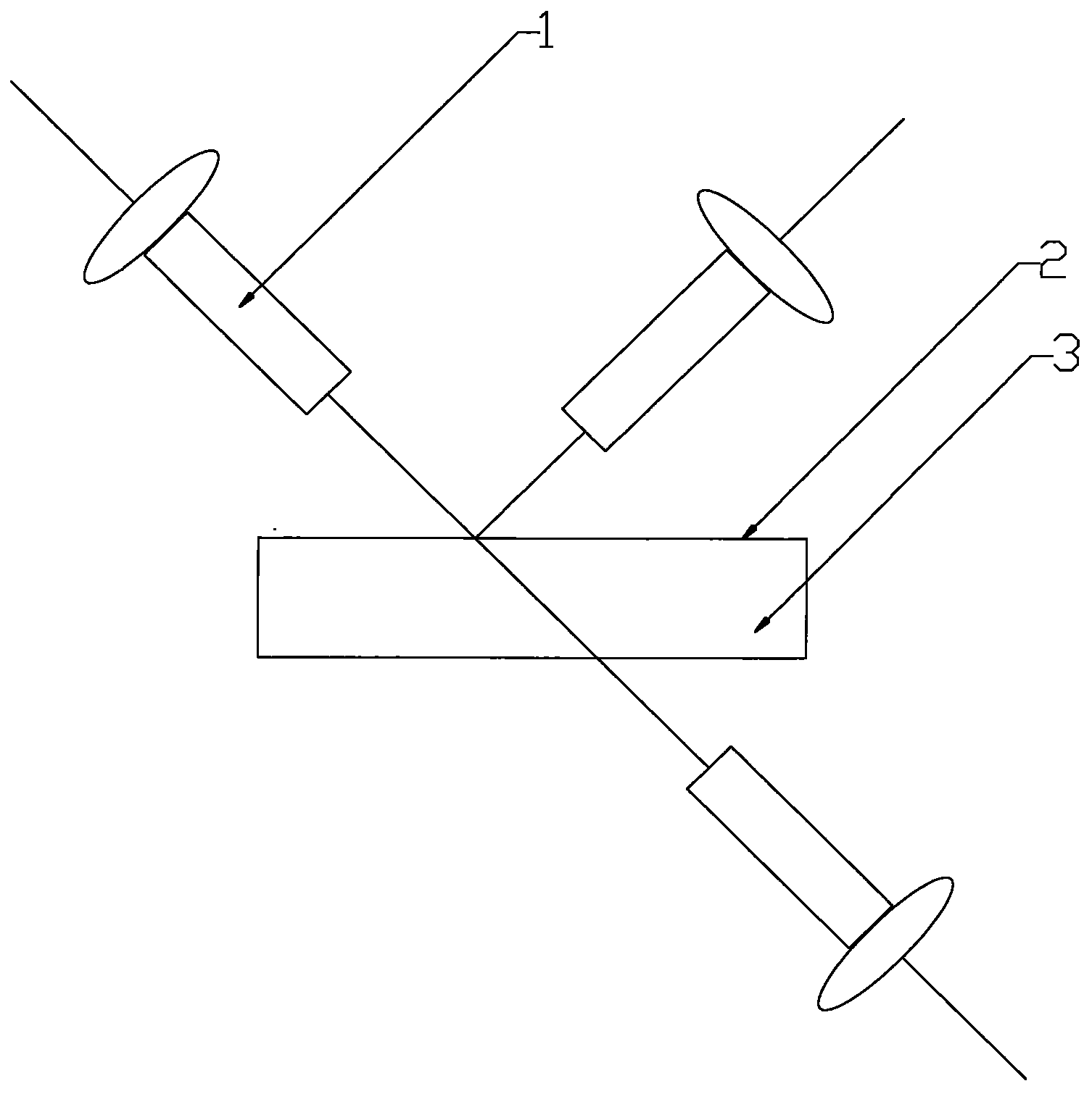
[0011] Below in conjunction with accompanying drawing, the present invention is described in detail, as figure 1 It is a schematic diagram of the optical switch structure of the present invention. As shown in the figure, the structure of the present invention includes three self-focusing lenses 1 connected with optical fibers. These three self-focusing lenses are respectively located in the light incident direction, reflection direction and transmission direction, and the incident The light will be reflected or transmitted on the optical filter inlaid on the turntable, and the A-type filter 2-A, B-type filter 2-B and light-absorbing filter 2-C are alternately inlaid on the turntable, as a specific wavelength Selective filter, A-type filter only transmits light with a wavelength of 1550nm, and B-type filter only transmits light with a wavelength of 1310nm. When the switch is working, the turntable rotates, and the light from the incident light self-focusing lens contains two wa...


PUM


Abstract

The invention discloses an optical switchgear, which comprises three grin lenses, a turntable and optical filters, wherein the three grin lenses are positioned on light paths of incident light, reflected light and transmitted light respectively; A type optical filters and B type optical filters are alternately embedded on the upper surface of the turntable, and only can transmit light waves of two specific wavelengths; and absorption filters are embedded between the A type and B type optical filters, can absorb the light waves of any wavelength and do not transmit and reflect the light. The switchgear structure of the invention overcomes the shortcoming that the conventional optical switchgear structure is complex and cannot realize a light wavelength selection function, and realizes reduction in cost.

Description

technical field [0001] The invention belongs to the field of optical communication, in particular to an optical switch used in optical fiber communication, which realizes the function of switching light waves of different wavelengths. Background technique [0002] With the development of communication technology, especially the development of Internet network, more users conduct various business exchanges on the network, resulting in a rapid increase in the amount of information, which puts forward higher requirements for network bandwidth. As a fast , The network information transmission method of huge amount of data has been widely used. Among light wave communication devices, optical switches are the most widely used type of communication devices. In recent years, new trends have emerged in the development of optical switches. First, the scale of optical switches is required to be larger and larger; second, the wavelength of optical switches can be conveniently selected;...

Claims


Application Information

Patent Timeline
IPC IPC(8): G02B26/08G02B6/35
Inventor 周权
Owner BEIJING ZHONGJING SYBO TECH
Learn More