Wire bonding apparatus

A wire bonding device and wire technology, applied to semiconductor devices, electrical components, circuits, etc., can solve problems such as damage to the lower part of the pad, eccentricity, and reduced quality of wire bonding, and achieve the effect of reducing inflow and gas flow

Active Publication Date: 2012-12-12
KAIJOO KK
View PDF1 Cites 0 Cited by
  • Summary
  • Abstract
  • Description
  • Claims
  • Application Information

AI Technical Summary

Problems solved by technology

Copper oxide is harder than copper, so there may be damage to the lower part of the pad at the junction of the copper ball and the pad of the IC chip
In addition, the oxidized copper balls will be discolored and off-centered, resulting in lower wire bonding quality

Method used


Image

  • Wire bonding apparatus
  • Wire bonding apparatus
  • Wire bonding apparatus

Examples


Embodiment )

[0150] (gas suction with second exhaust pipe)

[0151] The above-mentioned exhaust pipe flows out the inert gas from the first exhaust pipe 12 and the second exhaust pipe 20 to form an inert gas atmosphere, but as an embodiment, the inert gas can also flow out from the first exhaust pipe 12, and from the opposite The second exhaust pipe 20 sucks gas. Figure 8 It is a figure explaining drawing inert gas by the 2nd exhaust pipe.

[0152] Such as Figure 8 As shown, the inert gas discharged from the first exhaust pipe 12 flows through the space of the inert gas atmosphere, and is exhausted from the second exhaust The gas discharge port 22 of the tube 20 is sucked.

[0153] The inert gas flows out from the first exhaust pipe 12, and the gas is sucked from the opposing second exhaust pipe 20, thereby making the flow of the inert gas constant and forming a stable inert gas atmosphere. In addition, inert gas can be efficiently recovered.

[0154] In addition, since the opening ...


PUM


Abstract

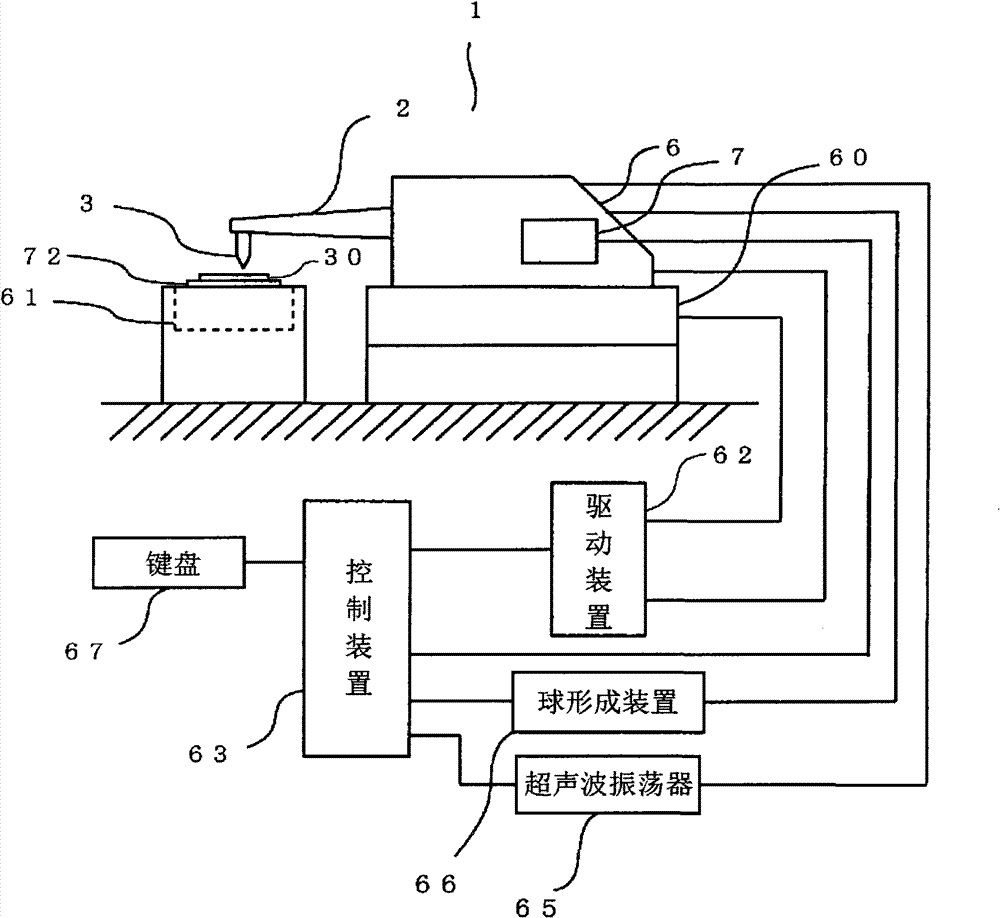
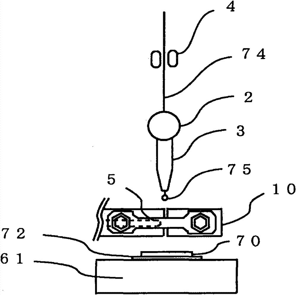
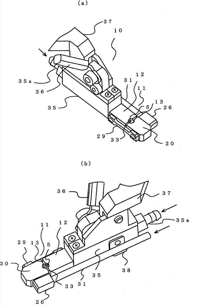
The present invention provides a wire bonding apparatus, capable of preventing FAB from oxidation and implementing stabilization of FAB in formation of FAB in a noble gas, and easily setting a discharging gap of a capillary pipe and a sparkle pole by a position adjusting mechanism and a size of a space of the noble gas. The apparatus includes: a pair of exhaust pipes (11, 20), which opening parts(13, 21) facing to each other spacing a front end of the capillary pipe (3) and having notching parts (13a, 21a) through which the front end of the capillary pipe can pass, the exhaust pipes are usedfor discharging the noble gas to the notching parts; the sparkle pole (5) configured to perform spark discharge to a wire from the capillary pipe in the exhaust pipes to form a ball; and a position adjusting unit for changing a distance between opening parts of the exhaust pipes to change a size of a space between the opening parts of the exhaust pipes, so as to change the size of the space of the noble gas.

Description

technical field [0001] The present invention relates to a wire bonding device using a copper wire, an aluminum wire, or the like, and specifically relates to a wire bonding device capable of forming a stable ball at a tip of a copper wire. Background technique [0002] In the assembly process of semiconductors, wire bonding using gold wires is a mainstream technique, but wire bonding using copper wires, which have a lower material cost than gold wires, has also become popular. However, in wire bonding using a copper wire, when balls are formed by spark discharge, copper and oxygen elements react to form copper balls of copper oxide. Since copper oxide is harder than copper, the lower portion of the pad may be damaged at the joint between the copper ball and the pad of the IC chip. In addition, the oxidized copper balls will be discolored and off-centered, resulting in lower wire bonding quality. Here, the ball formed at the tip of the lead wire by spark discharge is called...

Claims


Application Information

Patent Timeline
Patent Type & Authority Patents(China)
IPC IPC(8): H01L21/60
CPCH01L2224/45124H01L2924/01082H01L2224/78301H01L2924/01079H01L2924/01007H01L2924/01018H01L2924/01002H01L24/78H01L2924/14H01L2924/01005H01L2924/01033H01L2924/01006H01L2924/01029H01L2224/78268H01L2924/01013H01L2924/014H01L2224/45147H01L2924/00014H01L2224/48463H01L2924/00011H01L2224/45144H01L2224/78H01L2924/00H01L2924/00012H01L2924/00015
Inventor 石井志信吉野秀纪木村荣二
Owner KAIJOO KK
Why Eureka
Try Eureka