Full-differential same-phase parallel amplifying device for acquiring bioelectric signal

A bioelectrical signal and amplification device technology, applied in differential amplifiers, DC-coupled DC amplifiers, unidirectional transmission networks, etc., can solve problems such as easy baseline drift, complex circuits, and unsatisfactory conditions, and achieve significant economic and social benefits. Simple circuit structure, not easy to saturate the effect

Active Publication Date: 2011-03-30
EDAN INSTR
View PDF0 Cites 14 Cited by
  • Summary
  • Abstract
  • Description
  • Claims
  • Application Information

AI Technical Summary

Problems solved by technology

Due to the presence of a time constant circuit, the capacitor will be charged when the patient’s polarization voltage is relatively large and the output of the first stage is saturated. Assuming that the patient’s condition is stable at this time (the patient’s upper polarization voltage reaches a relatively small normal value), then It takes a very long time for the charge on the DC blocking capacitor to be released, and ECG signal acquisition cannot be performed during this period
Therefore, the signal output speed of the AC device is slow, and the baseline is easy to drift, and the baseline recovery is slow
The traditional AC amplification has the following disadvantages: the signal dynamic range is small; the circuit is very complex and noisy; the amplifier saturation and baseline recovery are slow (baseline drift) problems
[0004] The circuit is still relatively complex, and there are many amplification links, which is not good for

Method used


Image

  • Full-differential same-phase parallel amplifying device for acquiring bioelectric signal
  • Full-differential same-phase parallel amplifying device for acquiring bioelectric signal
  • Full-differential same-phase parallel amplifying device for acquiring bioelectric signal

Examples


Embodiment Construction

[0017] Below in conjunction with accompanying drawing, the present invention is described in further detail:

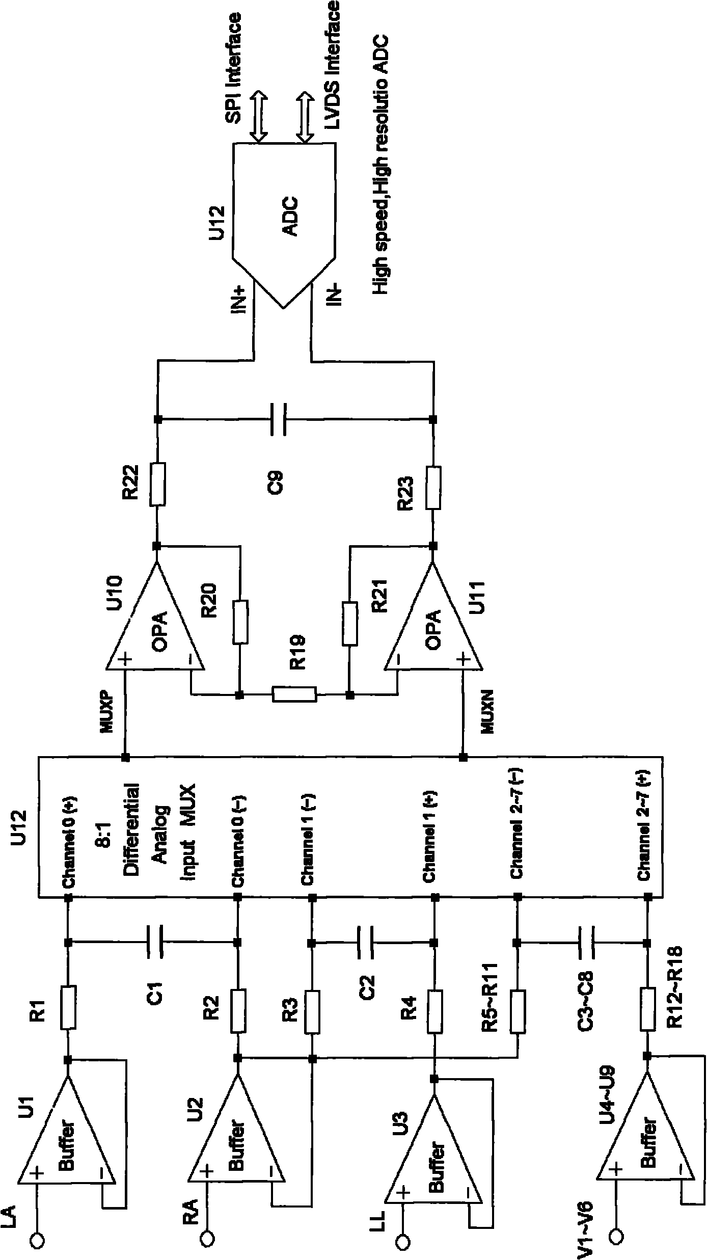
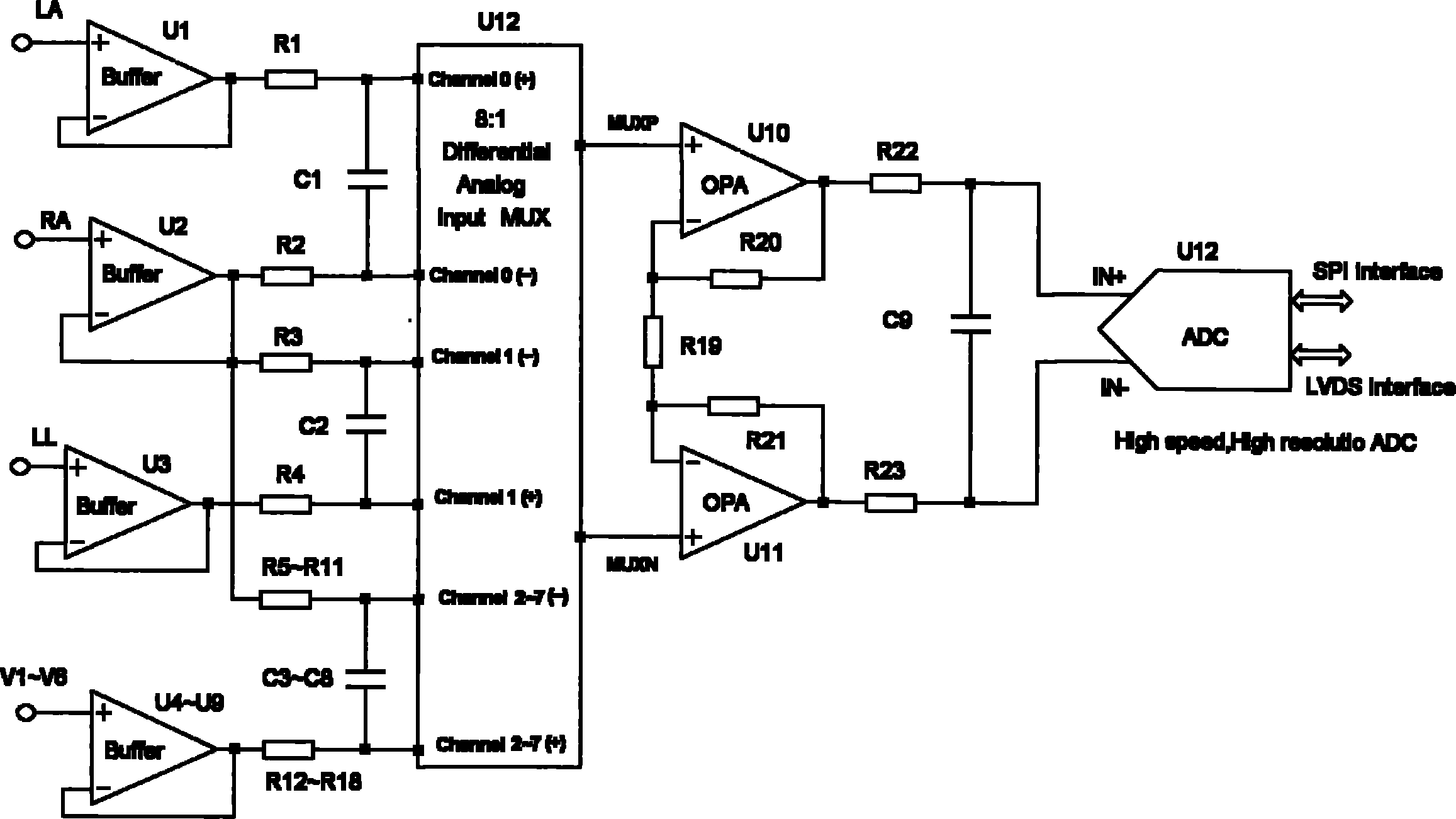
[0018] see figure 1 , The in-phase parallel differential DC amplifier circuit device includes an input buffer, a fully differential RC filter circuit, a channel selector, an in-phase parallel differential amplifier circuit, and an analog-to-digital conversion circuit. The biological signal after low-pass filtering by the differential filter circuit passes through the data selector and the in-phase parallel amplifying circuit to amplify the biological electrical signal and suppress the common mode signal, and then filter out the signal outside the high frequency band through the anti-aliasing filter network. The noise of the biological signal, the amplified signal is output after analog-to-digital conversion by the analog-to-digital conversion circuit.

[0019] Among them, the input buffer circuits U1~U9 have a total of 9 channels, each of which is composed of a gas d...


PUM


Abstract

The invention discloses a full-differential same-phase parallel amplifying device for acquiring a bioelectric signal. The amplifying device comprises an input buffer circuit, a differential filtering circuit, a data selector, a same-phase parallel amplifying circuit and an analog-digital conversion circuit which are connected sequentially. The input buffer circuit performs impedance conversion on the bioelectric signal first; the bioelectric signal subjected to low-pass filtering by the differential filtering circuit passes through the data selector and the same-phase parallel amplifying circuit; the bioelectric signal is amplified and a common-mode signal is suppressed; the noise of the bioelectric signal outside a signal high-frequency band is filtered through an anti-aliasing filtering network; and the amplified signal is subjected to analog-digital conversion by the analog-digital conversion circuit and then is output. The noise and common-mode suppression ratio can reach a high index, a base line is stable, a dynamic signal input range is wide, signals are difficult to saturate, and the device has high in reliability and can support perfect PACE detection. Meanwhile, the circuits are simple and are low in cost, and the device can be used for various bioelectric detection instruments and systems and has obvious economic benefit.

Description

technical field [0001] The invention relates to a device for collecting bioelectrical signals, in particular to a bioelectrical signal collecting device with full differential in-phase parallel amplification. Background technique [0002] As we all know, bioelectrical signal detection is carried out in the presence of strong background interference and the presence of patient polarization voltage. Due to the influence of strong interference (especially power frequency interference), instrumentation amplifiers are required. Bioelectrical signals are very weak and often need to be amplified by hundreds of times. When the electrode is in contact with the human skin, there is a polarization voltage, so the first-stage gain of the general amplifier is relatively small. It is necessary to isolate the polarization voltage with a resistance-capacitance circuit and then use the second-stage amplifier for amplification. Due to the existence of the time constant circuit, the capacitor...

Claims


Application Information

Patent Timeline
IPC IPC(8): H03H11/38H03F3/45
Inventor 向小飞胡寻桥谢锡城
Owner EDAN INSTR
Why Eureka
Try Eureka