Chip friction clutch

A technology of friction clutches and clutches, applied in the field of clutches, can solve problems such as waste, rotten threads, high material and processing costs, and achieve the effects of reducing processing costs, improving sealing effects, and reducing material costs

Active Publication Date: 2012-09-05
刘珍利
View PDF0 Cites 1 Cited by
  • Summary
  • Abstract
  • Description
  • Claims
  • Application Information

AI Technical Summary

Problems solved by technology

[0002] see Image 6 , the outer cover 1 and the end cover 19 of the existing disc friction clutch are usually formed by die-casting of aluminum alloy material, and the wall thickness of the end cover 19 is relatively thick, usually above 7mm. The combination of the end cover 19 and the outer cover 1 is The axial end faces are connected, in order to enable the end cover 19 to be fixed on the end face of the outer cover 1, four screw installation holes are evenly distributed on the end cover 19 of the clutch, and four screw holes are correspondingly arranged on the end face of the outer cover 1, The end cover 19 and the clutch cover 1 are fastened by four screws 21 to form an end face connection. There is a straight joint surface 20 between the end cover 19 and the cover 1. The radial length of the joint surface 20 is small, causing the end cover 19 to be closed. There is a radial straight gap in the oil chamber 10 of the oil chamber. In order to prevent the oil in the oil chamber 10 from being thrown out from the straight gap of the joint surface 20 under the centrifugal force of the high-speed rotation of the clutch, the existing clutch end cover 19 and the outer cover 1 The mating gaps of the coupling surfaces 20 between the clutches are sealed with paper pads 22, and the paper pads 22 are easily damaged after being soaked in engine oil, and the paper pads need to be replaced after the clutch is disassembled for maintenance.
And when the outer cover 1 processes the outer cover screw hole or when the end cover screw 21 is fastened, it is easy to cause thread rot and slippage, causing the whole clutch outer cover to be scrapped, resulting in waste
Moreover, the outer cover and end cover of the clutch are all made of aluminum alloy die-casting, and the material and processing costs are relatively high, which will inevitably increase the economic burden on manufacturers and users

Method used


Image

  • Chip friction clutch
  • Chip friction clutch
  • Chip friction clutch

Examples


Embodiment Construction

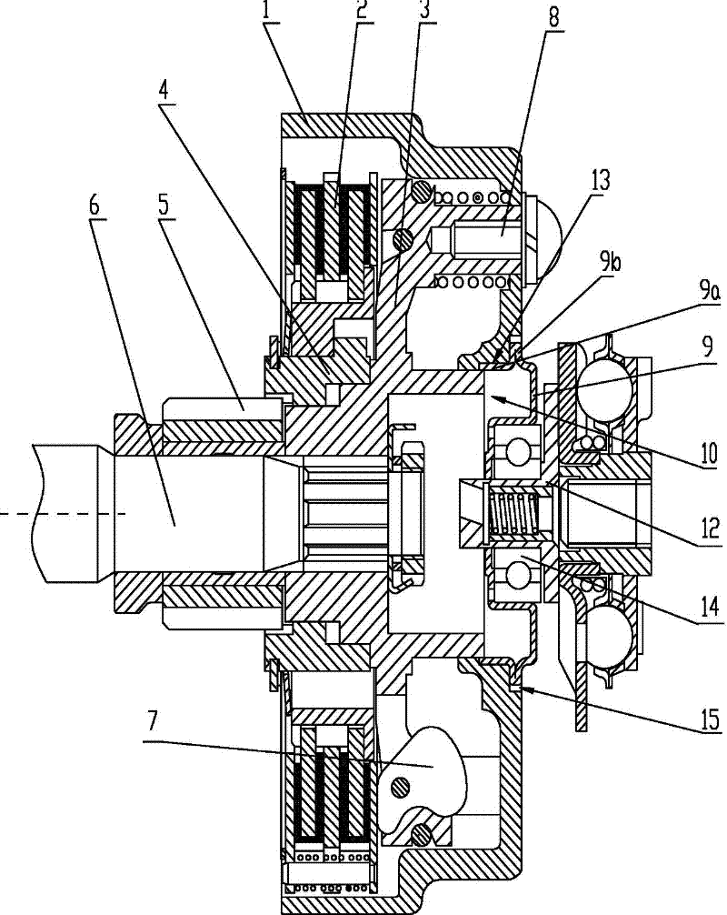
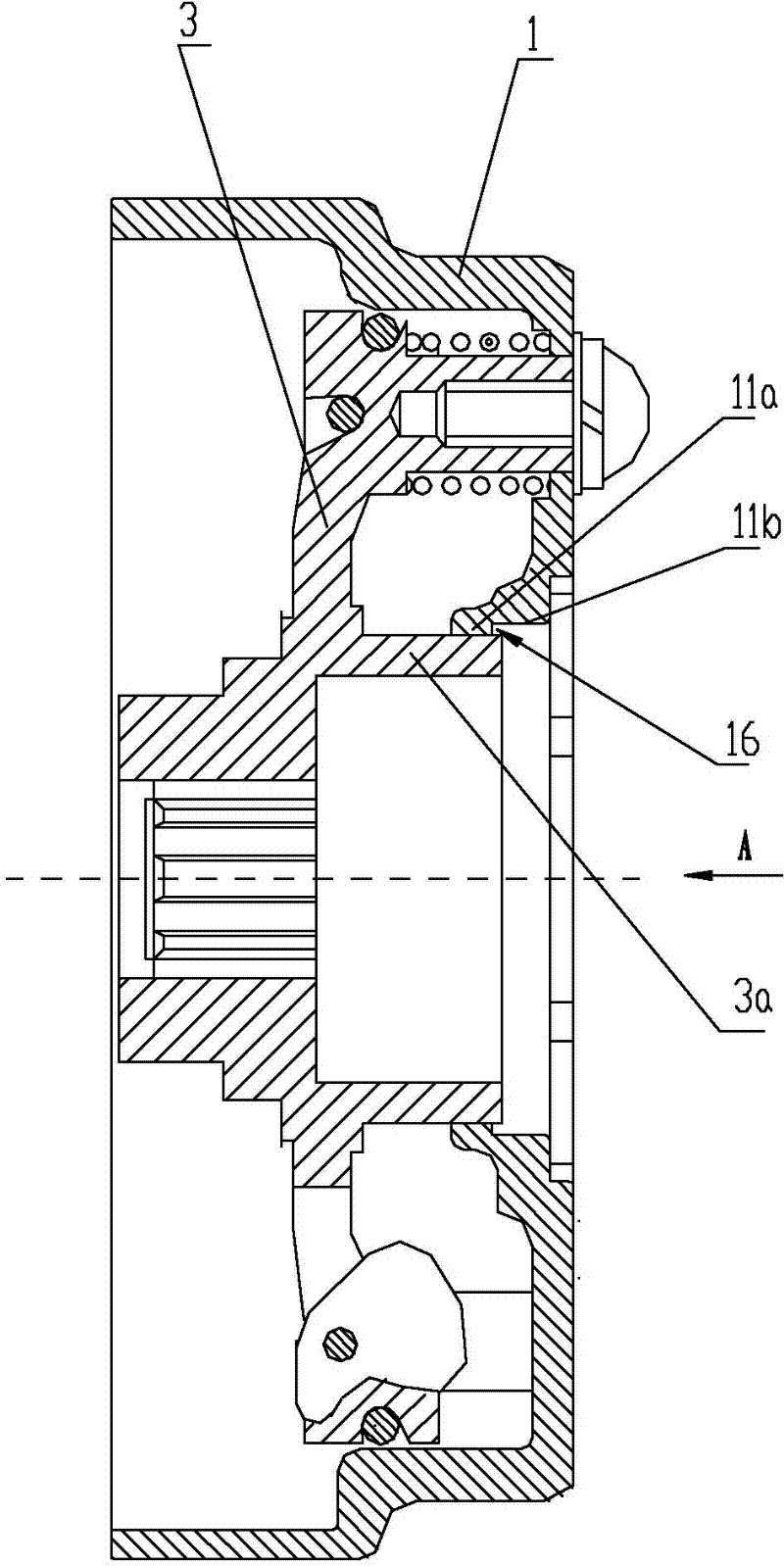
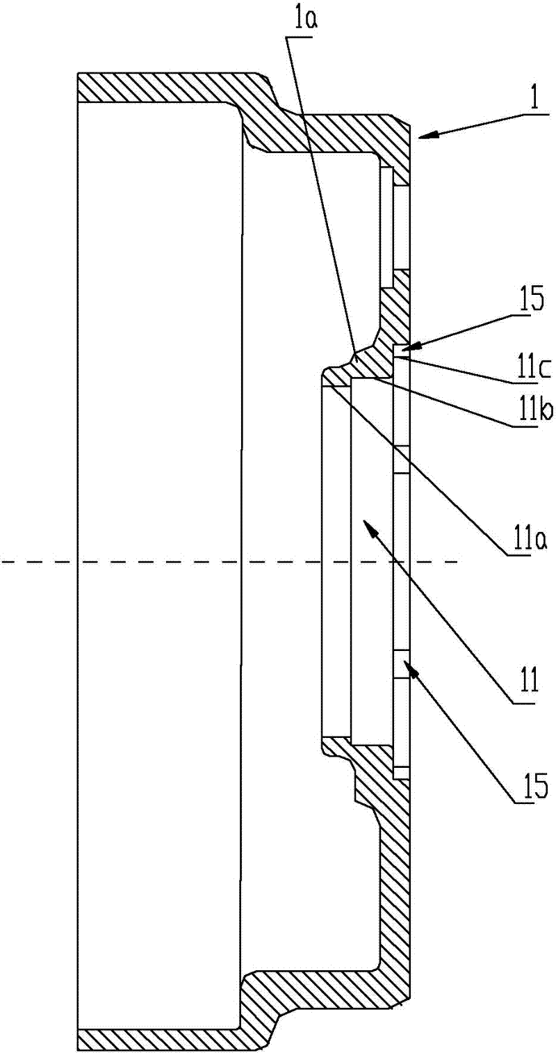
[0022] see Figure 1 to Figure 5 In an embodiment of the disc friction clutch of the present invention, the axial end wall of the cover cavity of the clutch housing 1 has an extension 1a extending axially into the cavity, and a central through hole 11 is set at the center of the extension 1a. A driving disk 3 is fixed and assembled in the housing cavity in the circumferential direction, the driving disk 3 is fixed to the end surface of the outer cover 1, and is fastened and connected from the end surface by a plurality of screws 8, and the driving disk 3 is used for splined connection with the rotating shaft 6 for power transmission. The driving disc 3 is relatively rotatably covered with a driven disc combination 4, the friction pair combination 2 of the clutch is assembled between the driven disc combination and the outer cover 1, and the driven disc combination 4 meshes with a transmission gear 5 located outside the outer cover 1, The transmission gear 5 is loosely fitted o...


PUM


Abstract

The invention discloses a chip friction clutch. A center through hole of an extension part of the axial end wall in a cavity of a clutch outer cover is a step hole. A first step section of the step hole is a small-diameter section. The hole wall of the small-diameter section is sleeved on a hollow cylinder which extends axially on a driving disc so as to form a ring-shaped groove between the inner wall of a second step section of the step hole and the extension end of the hollow cylinder. The center through hole of the clutch outer cover is covered by an end cover which is formed by carrying out drawing punch forming on a steel plate. The extension end of an axial extension part of the outer peripheral wall of the end cover, which extends toward the cavity of the clutch outer cover, is ininterference fit in the ring-shaped groove. A radial extension part which extends radially outwards and turns back and is formed on the axial extension part of the outer peripheral wall of the end cover is clamped and fixed in a third step section of the step hole of the clutch outer cover so as to form labyrinth sealing surfaces with a plurality of turns on the junction surfaces between the end cover and the driving disc and between the end cover and the clutch outer cover, wherein the third step section is a big-diameter section. The clutch can prevent machine oil from being thrown out of the junction surfaces, and the production cost of the clutch can be reduced.

Description

technical field [0001] The invention designs and a clutch, in particular to a disc friction clutch. Background technique [0002] see Figure 6 , the outer cover 1 and the end cover 19 of the existing disc friction clutch are usually formed by die-casting of aluminum alloy material, and the wall thickness of the end cover 19 is relatively thick, usually above 7mm. The combination of the end cover 19 and the outer cover 1 is The axial end faces are connected, in order to enable the end cover 19 to be fixed on the end face of the outer cover 1, four screw installation holes are evenly distributed on the end cover 19 of the clutch, and four screw holes are correspondingly arranged on the end face of the outer cover 1, The end cover 19 and the clutch cover 1 are fastened by four screws 21 to form an end face connection. There is a straight joint surface 20 between the end cover 19 and the cover 1. The radial length of the joint surface 20 is small, causing the end cover 19 to be...

Claims


Application Information

Patent Timeline
Patent Type & Authority Patents(China)
IPC IPC(8): F16D13/38F16D13/58
Inventor 刘珍利
Owner 刘珍利
Why Eureka
Try Eureka