Flue gas sampling device

A flue gas sampling and gas sampling technology, applied in the fields of detection and analysis, and gas sampling, can solve the problems of long-term work, difficult sampling pump, overload damage of sampling pipeline sampling pump, etc., and achieve the effect of long-term reliable work.

Active Publication Date: 2014-02-19
上海北分科技股份有限公司
View PDF5 Cites 0 Cited by
  • Summary
  • Abstract
  • Description
  • Claims
  • Application Information

AI Technical Summary

Problems solved by technology

[0005] There are one or more of the following problems in the prior art: the sampling pump has a short service life, the sampling pressure and flow rate are unstable, the sampling pipeline is blocked and the sampling pump is easily overloaded and damaged, and the sampling pump is difficult to work for a long time under high temperature conditions

Method used


Image

  • Flue gas sampling device
  • Flue gas sampling device
  • Flue gas sampling device

Examples


Embodiment 1

[0065] combine figure 1 and figure 2 Be explained.

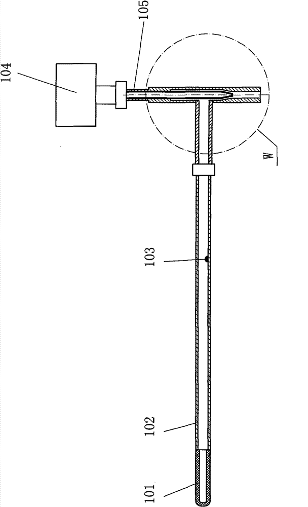
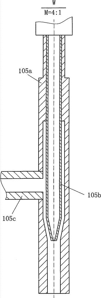
[0066] figure 1 is one of the schematic diagrams of the device of the present invention; figure 2 yes figure 1 The partial enlarged picture at W in the center, the magnification ratio is 4:1, this picture expresses the structure diagram of the jet injector for cross-section processing. Explanation of symbols in the figure: 101. filter; 102. hollow rod; 103. probe; 104. air source machine; 105. jet injector; 105a. injector main body;

[0067] Such as figure 1 As shown, the left front end of the hollow rod 102 is provided with a filter 101; the filter 101 is located in the most typical and representative smoke environment. The right end of the hollow rod 102 communicates with the injector body 105a through a transverse cylinder 105c.

[0068] When the air source machine 104 provides high-speed gas to the jet injector 105, the gas enters the upper part of the nozzle 105b (the first inlet end of the jet injector 105), a...

Embodiment 2

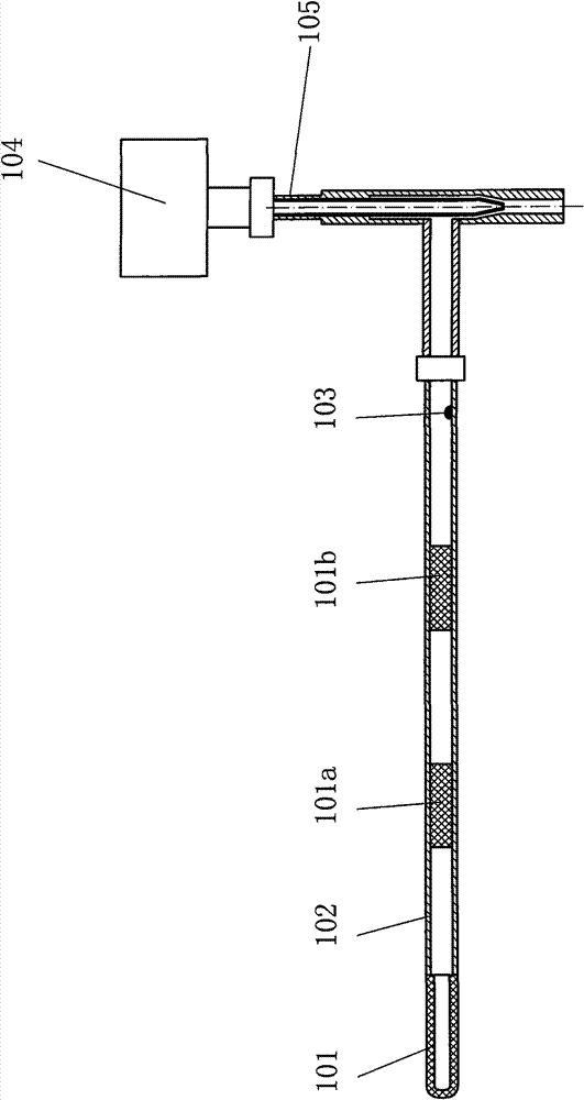
[0071] combine image 3 Be explained. image 3 Explanation of symbols in: 101. filter; 101a. second filter; 101b. third filter; 102. hollow rod; 103. probe; 104. air source machine; 105. jet injector.

[0072] In this example image 3 and in Example 1 figure 1 In comparison, the difference is that: figure 1 A single filter is used for filtering; and image 3 The three filters that play a role in filtering are the first filter 101, the second filter 101a, and the third filter 101b; the sample gas flows from the first filter 101, the second filter 101a, and the third filter in sequence 101b filtered through.

[0073] The third filter 101c, the probe 103, and the jet injector 105 are also arranged sequentially in the gas path through which the sample gas flows.


PUM


Abstract

The invention relates to the technical field of sampling, detection and analysis of gas and discloses a flue gas sampling device. For solving the problems of short service life and the like of a sampling pump, the invention provides the following technical scheme. The flue gas sampling device is characterized in that a driving mechanism comprises a gas source machine (104) for providing a gas source and a jet injector (105) for driving flue gas to flow in a drainage manner, wherein air current provided by the gas source machine (104) enters a spray nozzle (105b) from top to bottom and is sprayed out at the lower retracted part of the spray nozzle (105b) so as to form a vacuum trend, thereby attracting sampling gas to enter from the second gas inlet end of the jet injector (105); and two strands of air current is mixed in a hollow-out cavity and is exhausted to the atmosphere through the gas outlet end of the jet injector (105). The invention has the benefits that the jet injector is provided with a movable component without the maintenance, repair and replacement and can work reliably for a long term; the pressure and the flow speed of the sampling gas are stable; the phenomenon that fine particles are blocked can be avoided; and the jet injector made of all metal can bear high temperature of the flue gas.

Description

technical field [0001] The invention relates to the technical field of gas sampling, detection and analysis, in particular to a flue gas sampling device. [0002] The invention can be applied to high-temperature gas sampling for detection and analysis by subsequent devices; the invention is especially suitable for use in the working environment of collecting high-temperature sample gas from the chimney of a power plant. Background technique [0003] In the flue gas analysis instrument of the prior art, the method of collecting sample gas is mainly a mechanical method, relying on the sampling pump to extract the flue gas under a certain pressure and flow rate; after obtaining the sample gas, the analyzer further analyzes the sample gas. for detection and analysis. Generally speaking, the sampling probe is set at the place where the sample gas passes. [0004] Generally speaking, the existing technology has the following technical problems: the service life of the sampling p...

Claims


Application Information

Patent Timeline
Patent Type & Authority Patents(China)
IPC IPC(8): G01N1/22G01N1/34F04F5/16
Inventor 廖明君徐颖何盼
Owner 上海北分科技股份有限公司
Why Eureka
Try Eureka