Collimator device for small animal imaging

A collimator and small animal technology, applied in the direction of using aperture/collimator, equipment for radiological diagnosis, application, etc., can solve the problems of high cost and poor flexibility, and achieve low cost and high resolution Effect

Active Publication Date: 2011-04-13
TSINGHUA UNIV
View PDF3 Cites 18 Cited by
  • Summary
  • Abstract
  • Description
  • Claims
  • Application Information

AI Technical Summary

Problems solved by technology

However, although the existing dedicated small animal SPECT imaging system has strong specialization and high resolution, it is expensive and has poor flexibility.

Method used


Image

  • Collimator device for small animal imaging
  • Collimator device for small animal imaging
  • Collimator device for small animal imaging

Examples


no. 1 example

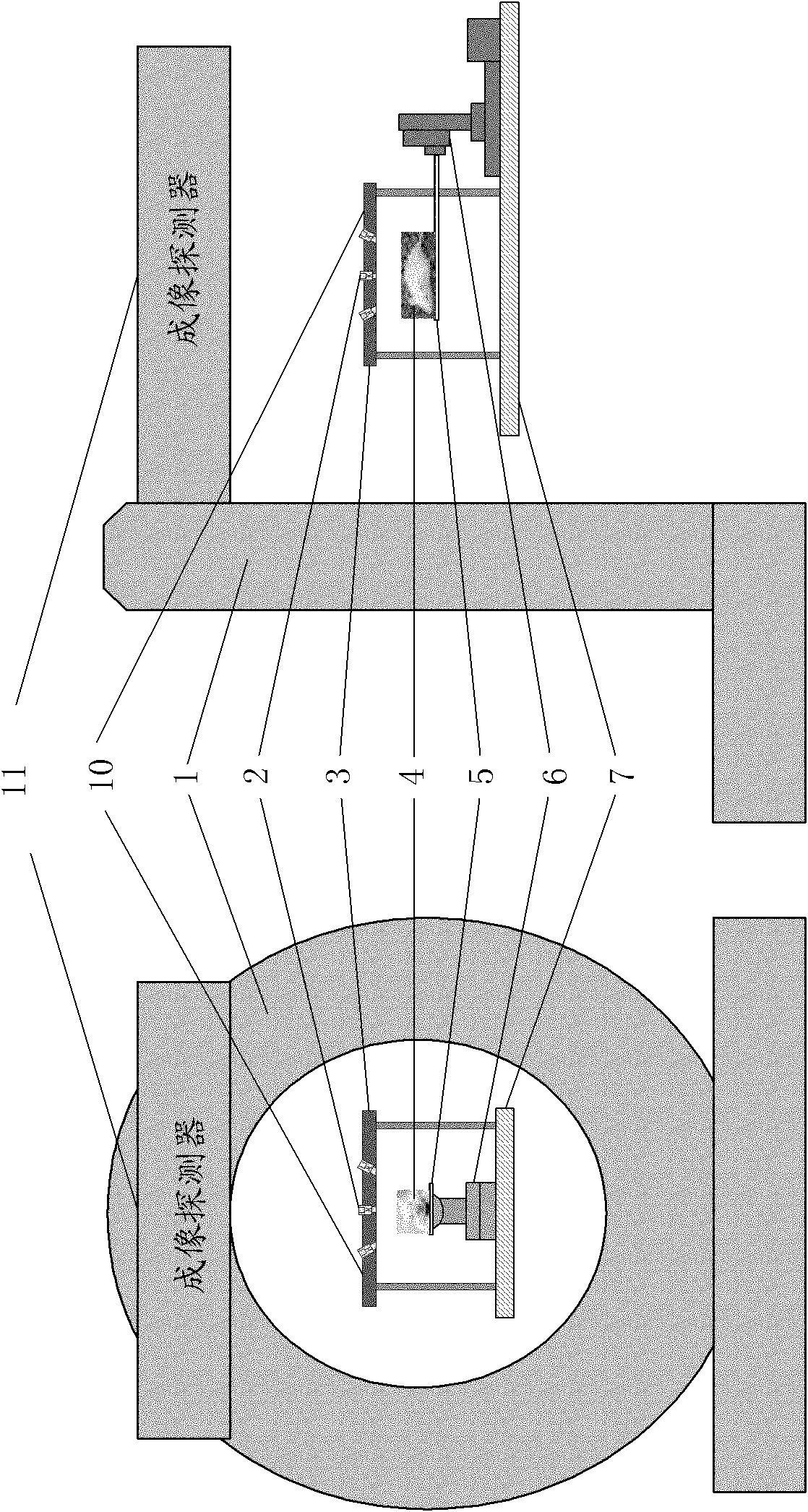
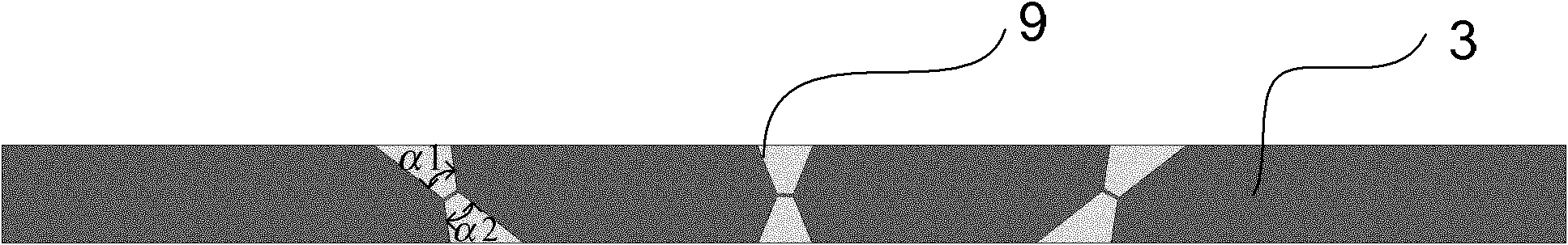
[0059] Such as image 3 As shown, the imaging hole 9 on the collimator plate 3 is composed of two opposite frustum-cone holes opening outward, and the cone-vertex angles of the above-mentioned two frustum-cone holes are equal. Specifically, the cone extension angle α of the first frustum hole 1 and the cone top angle α of the second frustum hole 2 equal. In one embodiment of the present invention, the imaging hole 9 can be processed into a knife shape (such as image 3 shown) or boat bottom shape (such as Figure 4 shown) pinhole. The pinhole diameter of the imaging hole 9 , the topping angle of the frustum of the cone, and the height of the frustum of the cone can all be processed according to the imaging requirements. Wherein, on the same collimator plate 3 , the positions and inclination angles of the imaging holes 9 on the collimator plate 3 may be different.

[0060] The collimator 10 can be constituted by one or more collimator plates 3 in the first embodiment desc...

no. 2 example

[0066] Such as Figure 5 As shown, the collimator plate 3 has a plurality of stepped imaging holes 9 , and a pinhole insert 2 is detachably embedded in each imaging hole 9 . Wherein, the pinhole insert 2 includes a pinhole part 21 and a shielding part 22 , and the pinhole part 21 is located at the lower end of the shielding part 22 . Wherein, the pinhole portion 21 is composed of two opposite frustum-cone holes opening outward, and the heights of the two frustum-cone holes are equal, and the cone extension angles are also equal. Such as Figure 6 As shown, the height h1 of the first frustum hole of each pinhole part 21 is equal to the height h2 of the second frustum hole, and the cone extension angle α of the first frustum hole 3 and the second frustum hole α 4 equal. The pinhole portion 21 can collimate the radioactive rays emitted from the object 4 to be measured. The shielding part 22 may be in a circular cylindrical structure, and is used for shielding the radioactive...


PUM


Abstract

The invention discloses a collimator device for small animal imaging, which comprises a scanning bed, a motion control platform, a collimator and an imaging detector, wherein the scanning bed is used for supporting and fixing an object to be detected; the motion control platform is used for controlling the scanning bed to move in a predetermined scanning track; the collimator is used for limiting the angles of radioactive rays emitted by each fault of the object to be detected; and the imaging detector is used for receiving the radioactive rays emitted by the object to be detected and limited with the angles through the collimator, forming an inverse amplified projection image of the object to be detected thereon, acquiring projection data of each fault of the object to be detected and performing fault reconstruction to acquire a three-dimensional fault image of the object to be detected. The collimator device has high flexibility by selecting different pinhole inserts and collimator plates and adjusting the distance between the collimator and the imaging detector, can realize multi-mode imaging of high-resolution imaging, high detection efficiency imaging, large-view small animal imaging and the like, and has imaging high resolution and low cost.

Description

technical field [0001] The invention relates to the technical field of radiation detection imaging, in particular to a collimator device for small animal imaging. Background technique [0002] ECT (Emission Computed Tomography, emission computed tomography) is an inspection method using radionuclides. Among them, the ECT method includes PET (Positron Emission Computed Tomography, Positron Emission Computed Tomography) and SPECT (Single-Photon Emission Computed Tomography, Single-Photon Emission Computed Tomography). [0003] Among them, PET technology injects radionuclides (such as F18, carbon 11, etc.) into the object to be tested, and reflects the metabolic activities of life through the accumulation of the substance in metabolism, so as to achieve the purpose of diagnosis. Clinical SPECT imaging is to obtain a three-dimensional image of the distribution of radiopharmaceuticals in the patient's body by imaging gamma rays emitted from the patient's body, thereby reflecting...

Claims


Application Information

Patent Timeline
Patent Type & Authority Applications(China)
IPC IPC(8): A61B6/03G21K1/02
CPCA61B6/508
Inventor 马天予刘亚强戴甜甜魏清阳王石金永杰
Owner TSINGHUA UNIV
Why Eureka
Try Eureka