
Optimally-designed test fixture for power module

A power module and test fixture technology, which is applied in the direction of measuring electricity, measuring devices, and measuring electrical variables, can solve the problems of test fixture influence and damage to the device under test, so as to improve reliability and accuracy, absorb voltage overshoot, The effect of reducing the probability of voltage breakdown

Active Publication Date: 2011-04-13
SHANGHAI DAOZHI TECH CO LTD
View PDF6 Cites 10 Cited by
  • Summary
  • Abstract
  • Description
  • Claims
  • Application Information

AI Technical Summary

Problems solved by technology

[0007] The invention aims to solve the problem of the influence of the inductance of the existing test fixture on the test and the damage of the device under test due to overvoltage caused by improper testing

Method used


Image

  • Optimally-designed test fixture for power module
  • Optimally-designed test fixture for power module
  • Optimally-designed test fixture for power module

Examples


Embodiment Construction

[0021] The present invention will be further described below in conjunction with the accompanying drawings and embodiments.

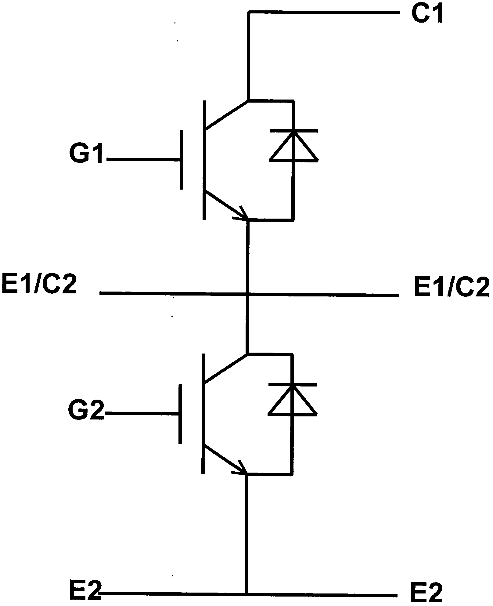
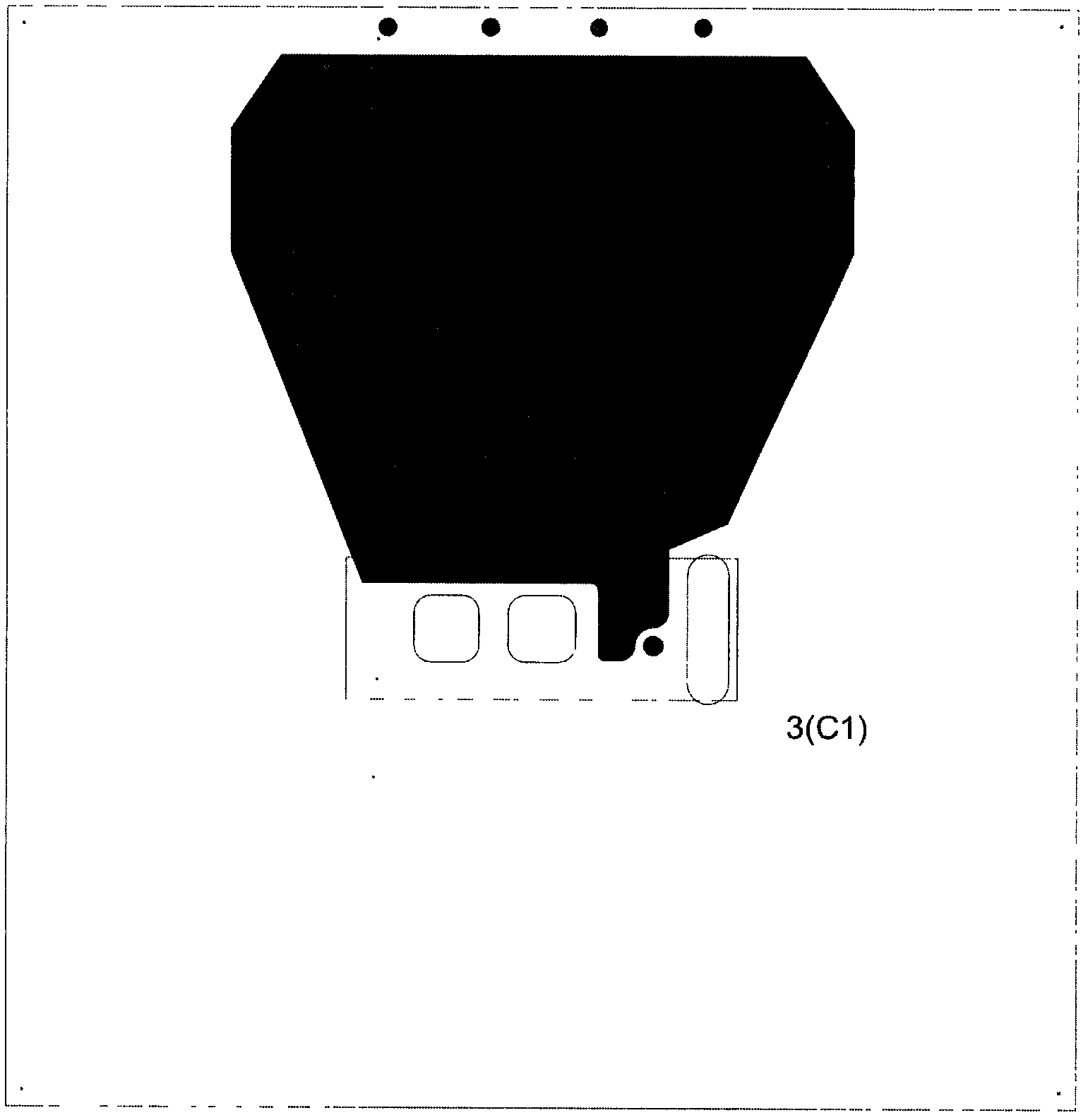
[0022] As shown in the figure, the present invention includes a substrate 3, a high-current probe 2 and a power circuit 4, a power connection plug 5 is provided on the side of the substrate 3, a signal terminal 6 is provided on the back of the substrate 3, and the high-current probe 2 is arranged on On the front side of the substrate 3, a laminated busbar is fixed on the substrate 3, and a power circuit 4 is etched on the laminated busbar.

[0023] The substrate 3 is made of materials with high strength and good insulation. Such as FR4 material with a thickness of 10mm. Ensure good mechanical strength and insulation performance of the mechanical support.

[0024] The high-current probe 2 is connected to the stacked bus bar. The power connection plug 5 is brazed on the stacked bus bar, and the signal terminal 6 is welded on the probe contact assembly ...


PUM


Abstract

The invention discloses an optimally-designed test fixture for a power module. The optimally-designed test fixture comprises a substrate, a heavy-current probe and a power loop, wherein a power wiring plug is arranged on the side of the substrate; a signal terminal is arranged on the back surface of the substrate; the heavy-current probe is arranged on the front surface of the substrate; a laminated bus bar is fixed on the substrate; and a power loop is etched on the laminating bus rank. The optimally-designed test fixture is suitable for testing the power module.

Description

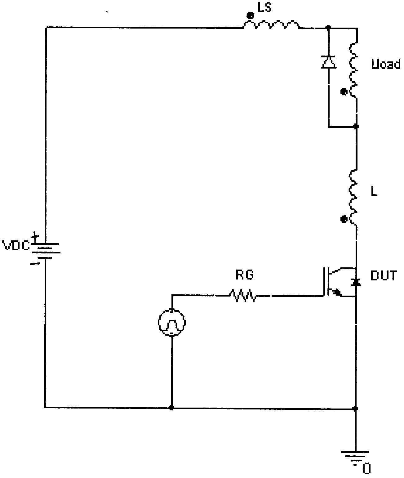
technical field [0001] The invention belongs to the testing field of semiconductor power modules, in particular to an optimally designed power module testing fixture. Background technique [0002] Power semiconductor modules have been increasingly used in various occasions, such as: industrial frequency converters, welding power supplies, locomotive traction, wind power generation and other occasions. [0003] The development and use of high-power modules have higher and higher requirements for test results. If the device under test is not tested properly, it may be damaged due to overvoltage. This is because the voltage and current stress of the power device switching action has a very large relationship with the parasitic inductance in the main circuit. When the power module is at a certain di / dt, the generated voltage spike is proportional to the size of the parasitic inductance. As shown in Figure (1), when the device is turned off, the external conductor parasitic ind...

Claims


Application Information

Patent Timeline
Patent Type & Authority Applications(China)
IPC IPC(8): G01R1/02
Inventor 戴志展李冯
Owner SHANGHAI DAOZHI TECH CO LTD
Learn More