
Building method for electric drive system hardware-in-the-loop simulation device

A technology of electric drive and system hardware, applied in the field of hardware-in-the-loop real-time simulation, which can solve the problems of low real-time performance

Inactive Publication Date: 2011-04-13
SHANGHAI UNIV
View PDF5 Cites 25 Cited by
  • Summary
  • Abstract
  • Description
  • Claims
  • Application Information

AI Technical Summary

Problems solved by technology

[0004] In addition, real-time simulation has high requirements on the accuracy of the motor system model, but for the processor-based real-time simulation system of the motor system, the more accurate the model, the more time the calculation will consume, and the lower the real-time performance

Method used


Image

  • Building method for electric drive system hardware-in-the-loop simulation device
  • Building method for electric drive system hardware-in-the-loop simulation device
  • Building method for electric drive system hardware-in-the-loop simulation device

Examples


Embodiment 1

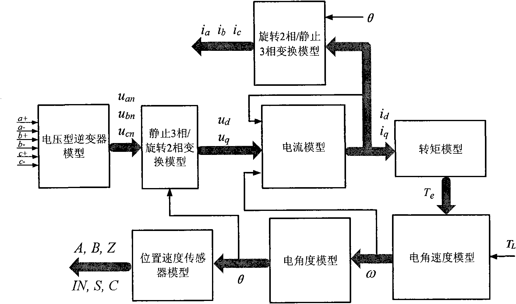
[0068] refer to figure 1 , the construction method of the hardware-in-the-loop simulation device of the electric drive system is: use the hardware description language VerilogHDL to model the converter, motor and position speed sensor in the electric drive system, and then integrate them into an FPGA chip. The FPGA chip used is produced by Altera Corporation of the United States, and the model is EP3C40Q240C8N. The FPGA chip and the interface circuit form a virtual motor printed circuit board, and the virtual motor printed circuit board is connected with the electric drive system controller printed circuit board to form a hardware-in-the-loop simulation device for the electric drive system. The DSP chip used by the power transmission system controller is produced by American TI Company, the model is TMS320F2812. The specific implementation steps are:

[0069] (1) Using the hardware description language Verilog HDL to model the converter in the electric drive system.

[007...

Embodiment 2

[0078] This embodiment is basically the same as Embodiment 1, and the special features are as follows: Reference figure 2 , the converter model is: receiving six PWM signals a + , a - , b + , b - , c + , c - , calculate the three-phase phase voltage u of the motor by the following formula an , u bn , u cn .

[0079] u an = u dc 6 [ 2 ( a + - a - ) - ( b + - b - ) - ( c + - c - ) ]

[0080] u bn = u d...


PUM


Abstract

The invention relates to a building method for an electric drive system hardware-in-the-loop simulation device. A converter, a motor and a position and speed sensor in a power transmission system are modeled through a hardware description language Verilog HDL and then are integrated into a field programmable gate array (FPGA) chip. The FPGA chip and an interface circuit form a virtual motor printed circuit board. The virtual motor printed circuit board is connected with an electric drive system controller printed circuit board to form the electric drive system hardware-in-the-loop simulation device. By the method, hardware-in-the-loop real-time simulation on an electric drive system can be performed and the quick development and product test of the electric drive system can be realized; moreover, the method has the characteristics of energy conservation, safety and low cost.

Description

technical field [0001] The invention relates to a hardware-in-the-loop real-time simulation technology, in particular to a construction method of an FPGA-based hardware-in-the-loop simulation device for an electric drive system. Background technique [0002] Real-time simulation technology is currently used in aerospace, military, and automotive industries. Compared with offline simulation technology, real-time simulation technology can realize the simulation of functions such as control interruption and delay, and is superior to offline simulation in terms of real-time and realistic approximation. At present, real-time simulation technology is divided into two categories: rapid control prototyping and hardware-in-the-loop. Rapid control prototyping technology uses virtual controllers and real control objects, and hardware-in-the-loop technology uses virtual control objects and real controllers. Constructing an FPGA-based hardware-in-the-loop simulation device for half-in-th...

Claims


Application Information

Patent Timeline
IPC IPC(8): G05B17/02H02P23/00
Inventor 黄苏融高瑾张琪刘畅罗志武
Owner SHANGHAI UNIV
Learn More