Electrochemical accumulator and vehicle comprising an electrochemical accumulator
A technology for vehicles and batteries, applied in the field of vehicles, can solve the problems of sudden reaction of battery cells, ignition of battery cells, harm to people and the environment, etc., and achieve the effects of favorable cost, improved efficiency and high production cost
- Summary
- Abstract
- Description
- Claims
- Application Information
AI Technical Summary
Problems solved by technology
Method used
Image

Examples
Embodiment Construction
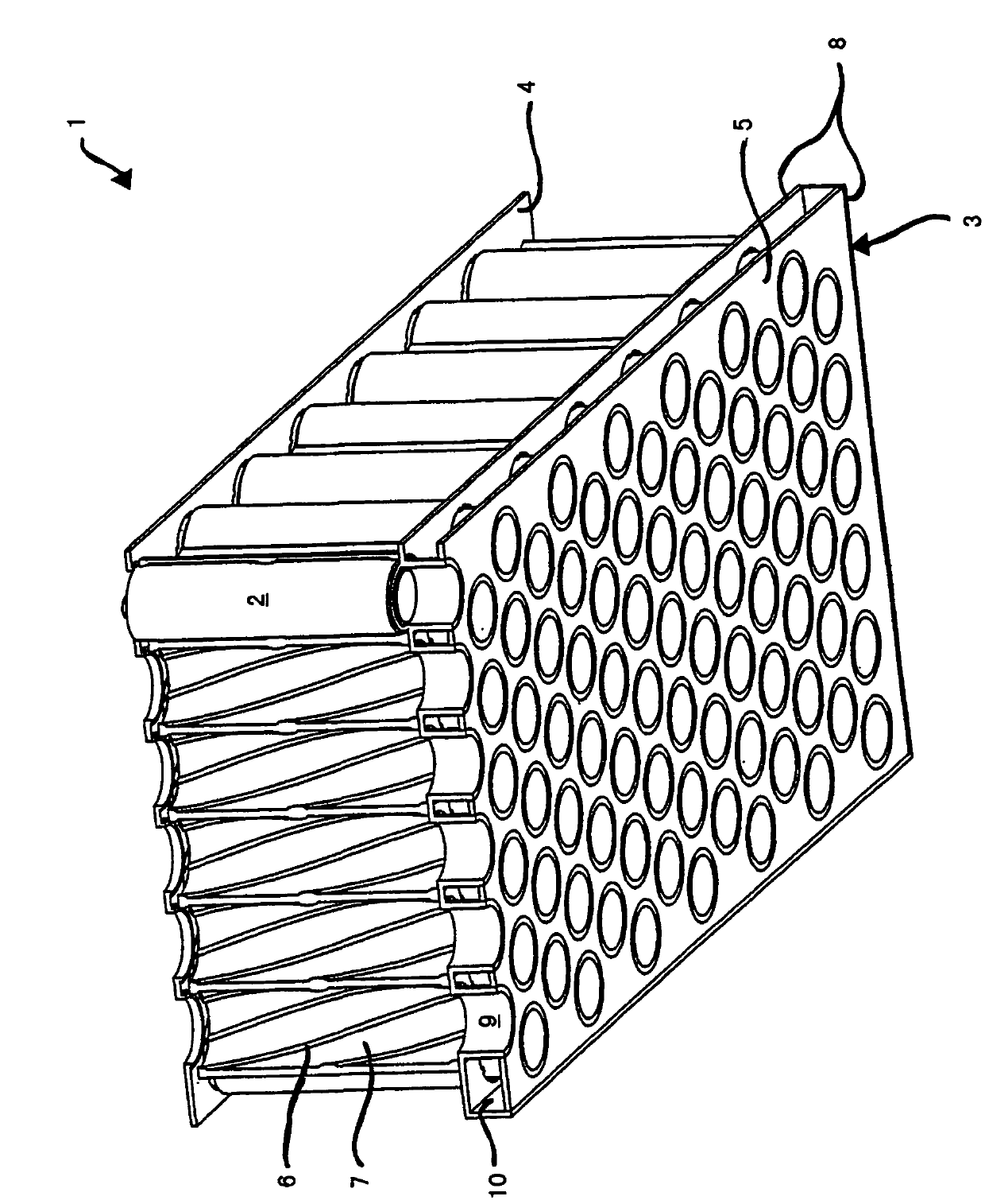
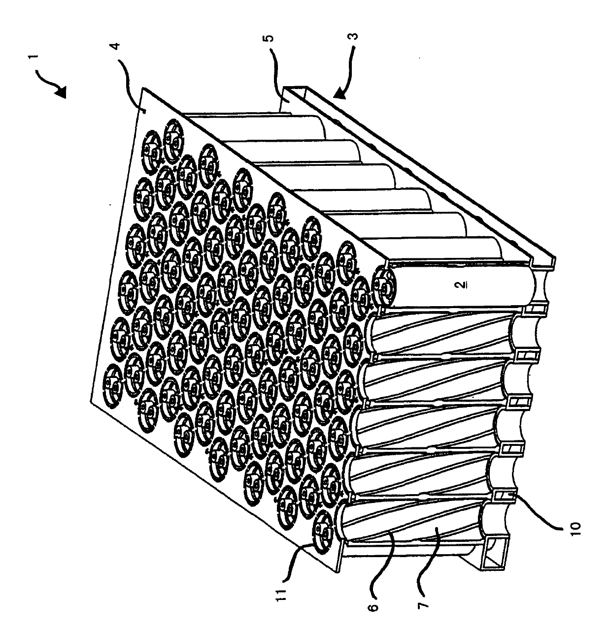
[0027] exist figure 1 A module of a plurality of galvanic cells 2 (hereinafter simply referred to as cells) is shown in .
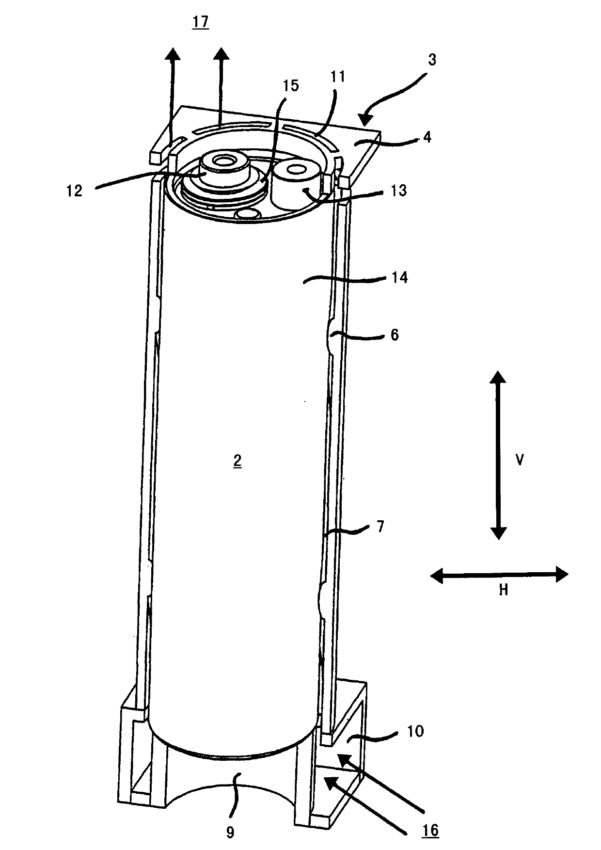
[0028] The battery cell 2 is a cylindrically wound circular battery cell. The wound assembly includes a positive electrode (not shown) and a negative electrode (not shown) with a separator and non-aqueous electrolyte disposed between the positive and negative electrodes. The present battery cell 2 is a lithium-ion battery cell.
[0029] The battery unit 2 is fixed in the bracket 3 . The bracket 3 is made of plastic.
[0030] The frame 3 has a single base plate 4 and a double base plate 5 . The single base plate 4 and the double base plate 5 are connected to each other by means of connecting strips 6 in such a way that they are spaced apart from each other and parallel to each other. A channel 7 is formed between every two connecting bars 6 . These channels 7 form the cooling air space of the accumulator according to the invention. Cooling air for c...
PUM
 Abstract
Description
Claims
Application Information
 - R&D
- Intellectual Property
- Life Sciences
- Materials
- Tech Scout
- Unparalleled Data Quality
- Higher Quality Content
- 60% Fewer Hallucinations
Browse by: Latest US Patents, China's latest patents, Technical Efficacy Thesaurus, Application Domain, Technology Topic, Popular Technical Reports.
© 2025 PatSnap. All rights reserved.Legal|Privacy policy|Modern Slavery Act Transparency Statement|Sitemap|About US| Contact US: help@patsnap.com