Sinter cooler lump ore braking system

A cooling machine and sintering technology, applied in the metallurgical field, can solve the problems of low screening efficiency, large time span, easy dew and sticky dust, etc., and achieve a simple, reliable and practical system, improved screening efficiency, and easy interlock control Effect

Inactive Publication Date: 2012-04-18
河南济源钢铁(集团)有限公司
View PDF0 Cites 0 Cited by
  • Summary
  • Abstract
  • Description
  • Claims
  • Application Information

AI Technical Summary

Problems solved by technology

However, in the process of mining, granulation, stockpiling, and transportation of lump ore, due to the long distance (mine fire transport to the port of shipment, ship shipment to the unloading port, fire transport to the raw material yard of the steel company), the time span is long (experienced Rain and snow weather in different seasons), stacked in the open air, so the powder content is high and the water content is high
During the sieving process, the lump ore is easy to block the sieve hole, which seriously affects the production of the blast furnace. The compaction is thick, which leads to low screening efficiency, and there are still a large number of ore powders <5mm entering the blast furnace, which affects the normal operation of the blast furnace and increases energy consumption; b. The water content of lump ore is mostly 6-10%, especially in rain and snow In the next season, the temperature of the top of the blast furnace will be lowered to a dew point temperature below 100°C, which will easily condense and stick to dust, which will affect the normal and safe operation of the follow-up dry dust removal gas system

Method used


Image

  • Sinter cooler lump ore braking system
  • Sinter cooler lump ore braking system
  • Sinter cooler lump ore braking system

Examples


Embodiment 1

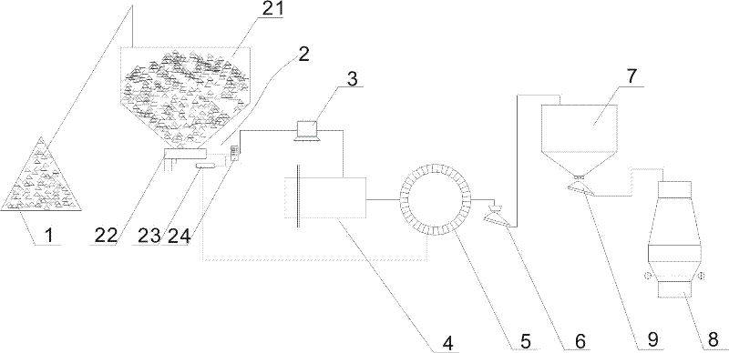
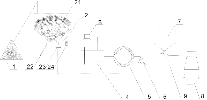
[0017] Such as figure 1 As shown, it consists of lump ore stockpile 1, lump ore proportioning device 2, computer 3, sintering machine 4, ring cooler 5, cold ore screen 6, blast furnace elevated bin 7, and blast furnace 8 in sequence. , described lump ore proportioning device 2 comprises lump ore upper hopper 21, lump ore quantitative feeding device 22, lump ore metering device 23, lump ore metering control cabinet 24, lump ore quantitative feeding device 22 is arranged on Below the discharge port of the lump ore upper silo 21, the lump ore metering device 23 is arranged below the lump ore quantitative feeding device 22, and the lump ore quantitative feeding device 22, the lump ore metering device 23 and the sintering machine 4 are respectively connected with the lump ore metering device. The control cabinet 24 is connected, and the lump ore metering device 23 is also connected with the annular cooler 5; a vibrating screen 9 is arranged between the blast furnace elevated bunker...

Embodiment 2

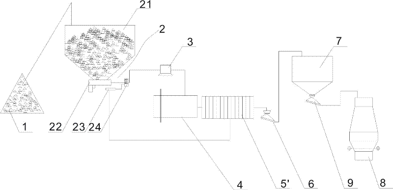
[0020] Such as figure 2 As shown, the annular cooler 5 in Embodiment 1 is replaced by a strip cooler 5', and the others are the same as in Embodiment 1.


PUM


Abstract

The invention belongs to the technical field of metallurgy and discloses a sinter cooler lump ore braking system. A lump ore material pile, a lump ore proportional adding device, a computer, a sinter, a cooler, a cold griddle, a blast furnace overhead bin and a blast furnace are sequentially connected to form the system, wherein the lump ore proportional adding device comprises a lump ore feedingbin, a quantitative lump ore feeding device, a lump ore metering device and a lump ore metering control cabinet; the quantitative lump ore feeding device is arranged below the discharge hole of the lump ore feeding bin; the lump ore metering device is arranged below the quantitative lump ore feeding device; the quantitative lump ore feeding device, the lump ore metering device and the sinter are respectively connected with the lump ore metering control cabinet; and the lump ore metering device is also connected with the cooler. The system provided by the invention has simple structure, recycles waste heat of the cooler for drying and dehydrating wet lump ore, and finally cools to about 80 DEG C, thus increasing the temperature of charged lump ore, maintaining the reasonable temperature atthe blast furnace top to be 100-170 DEG C, and prolonging the service life of a bag-type dust collector in follow-up processes.

Description

technical field [0001] The invention belongs to the technical field of metallurgy, in particular to a system for roasting lump ore with a sinter cooler. Background technique [0002] In iron and steel complexes, blast furnaces can be directly equipped with lump ore, which can effectively reduce costs. However, in the process of mining, granulation, stockpiling, and transportation of lump ore, due to the long distance (mine fire transport to the port of shipment, ship shipment to the unloading port, fire transport to the raw material yard of the steel company), the time span is long (experienced rainy and snowy weather in different seasons) and stacked in the open air, so the powder content is high and the water content is high. During the sieving process, the lump ore is easy to block the sieve hole, which seriously affects the production of the blast furnace. The compaction is thick, which leads to low screening efficiency, and there are still a large number of ore powder...

Claims


Application Information

Patent Timeline
Patent Type & Authority Patents(China)
IPC IPC(8): C22B1/00C22B1/26
Inventor 王方军张振江张瑞甫
Owner 河南济源钢铁(集团)有限公司
Why Eureka
Try Eureka