Electron emitter and electron emitting element

An electron emitter and electron emission technology, applied in electrical components, discharge tube/lamp parts, circuits, etc., can solve problems such as poor electron emission ability, achieve large emission current, improve field emission performance, and reduce electric field shielding effect of effect

Active Publication Date: 2011-04-20
TSINGHUA UNIV +1
View PDF4 Cites 0 Cited by
  • Summary
  • Abstract
  • Description
  • Claims
  • Application Information

AI Technical Summary

Problems solved by technology

Therefore, when using this kind of carbon nanotube long wire as an electron emitter, the electron emission end of the electron emitter is a flat structure, so its electron emission ability is relatively poor.

Method used


Image

  • Electron emitter and electron emitting element
  • Electron emitter and electron emitting element
  • Electron emitter and electron emitting element

Examples


preparation example Construction

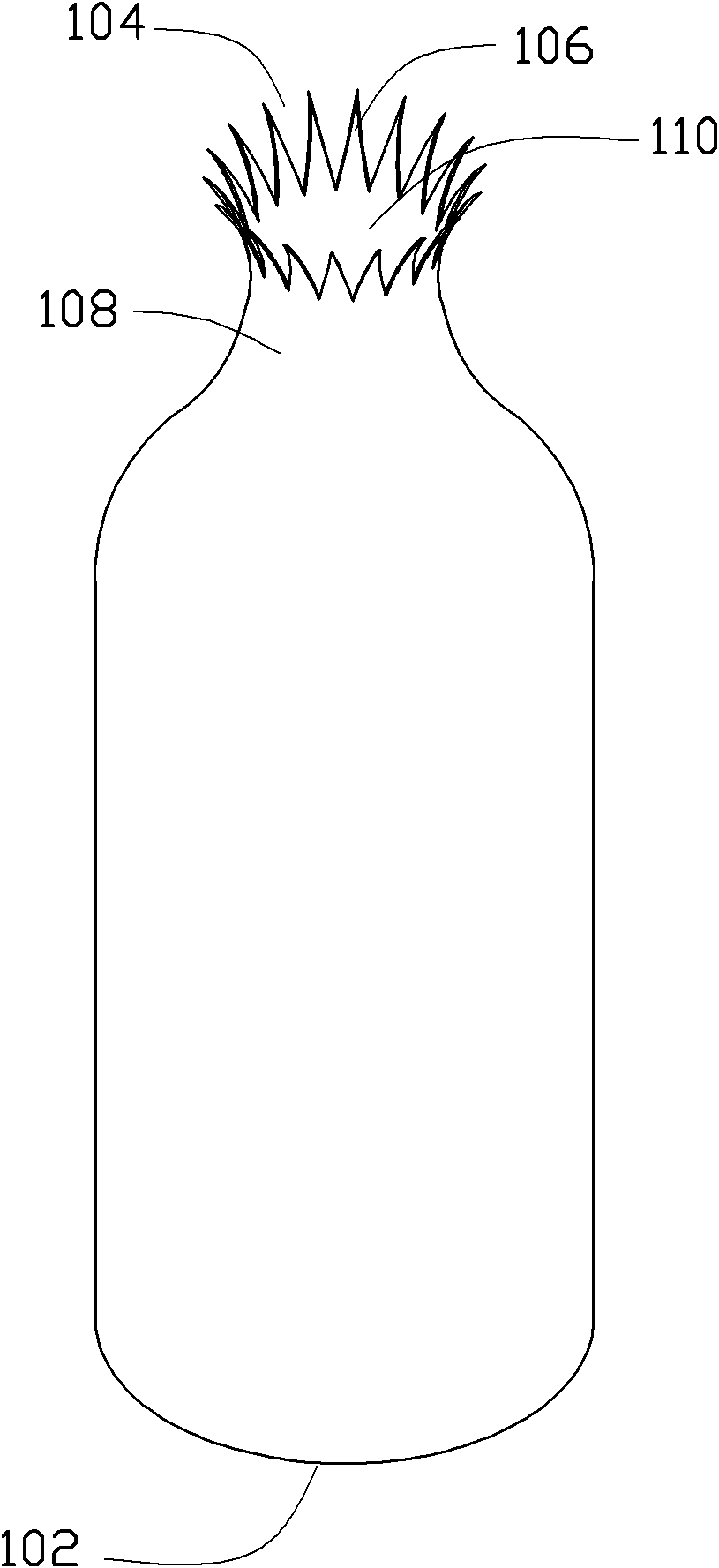
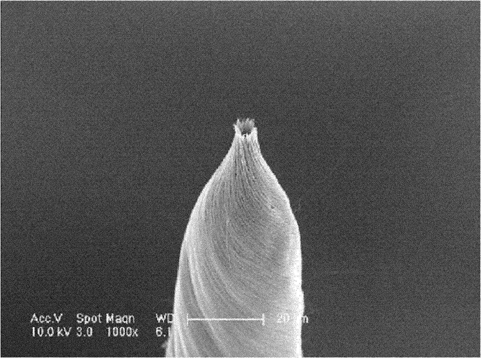
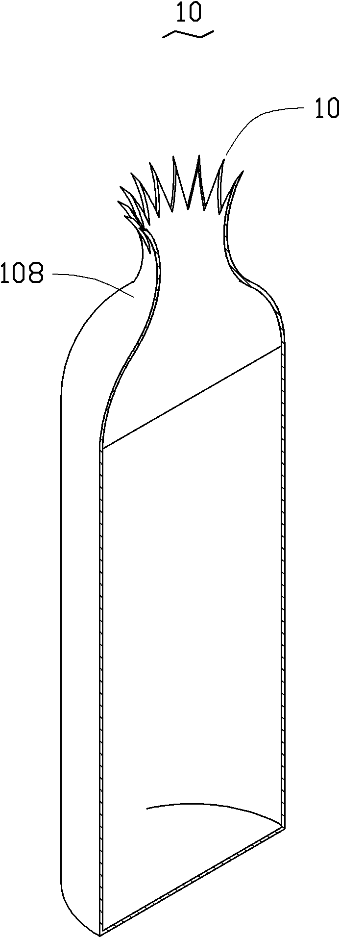
[0037] The preparation method of the electron emitter 10 includes the following steps: (S10) providing a linear support; (S20) providing at least one carbon nanotube film or at least one carbon nanotube wire, and the at least one carbon nanotube film or At least one carbon nanotube wire is wound on the surface of the linear support to form a carbon nanotube layer; (S30) removing the linear support to obtain a tubular carbon nanotube preform surrounded by the carbon nanotube layer; And (S40) fusing the tubular carbon nanotube preform to form the electron emitter.

[0038] In step (S10), the linear support body can not only rotate around its central axis but also move linearly along the direction in which the central axis extends under the control of a control device.

[0039] The material of the linear support can be a simple metal, a metal alloy, or a polymer material. The elemental metal includes gold, silver, copper or aluminum, etc., and the metal alloy includes copper-tin...


PUM


Abstract

The invention provides an electron emitter, which comprises a carbon nanometer tube tubular structure, wherein the carbon nanometer tube tubular structure is provided with a hollow linear axes and is formed by a plurality of carbon nanometer tubes surrounding the hollow linear axes, and a plurality of electron emitting sharp ends extend along one end of the linear axes of the carbon nanometer tube tubular structure. The electron emitter can be applied to field emission electron devices, scanning electron microscopes and transmission electron microscopes. The invention also relates to an electron emitting element.

Description

technical field [0001] The invention relates to an electron emitter and an electron emission element, in particular to an electron emitter and an electron emission element based on carbon nanotubes. Background technique [0002] Carbon Nanotube (CNT) is a new type of carbon material, which was discovered by Japanese researcher Iijima in 1991, please refer to "Helical Microtubules of Graphitic Carbon", S.Iijima, Nature, vol.354, p56 (1991) . Carbon nanotubes have excellent electrical conductivity, good chemical stability and large aspect ratio, and they have a tip surface area that is almost close to the theoretical limit (the smaller the tip surface area, the more concentrated its local electric field), so carbon nanotubes in the field The field of emitting vacuum electron sources has potential application prospects. Current studies have shown that carbon nanotubes are one of the best known field emission materials. Its tip size is only a few nanometers to tens of nanomete...

Claims


Application Information

Patent Timeline
Patent Type & Authority Applications(China)
IPC IPC(8): H01J1/304
CPCH01J1/304H01J2201/30469
Inventor 魏洋范守善
Owner TSINGHUA UNIV
Why Eureka
Try Eureka