Instrument and method for testing stratum in-situ thermal property of ground source heat pump and heat exchange quantity of buried pipe

A technology of ground source heat pump and buried pipe, which is applied in the field of testing the ground source heat pump buried pipe system of the new technology of HVAC, which can solve the problem of not being able to simulate the heat transfer and thermal conductivity test at the same time, increasing the system volume, and inconvenient transportation And other issues

Inactive Publication Date: 2011-04-27
NANJING UNIV +1
View PDF0 Cites 33 Cited by
  • Summary
  • Abstract
  • Description
  • Claims
  • Application Information

AI Technical Summary

Problems solved by technology

[0005] At present, many scientific research institutes or schools in China have developed formation thermal response testers, but the existing equipment has the following deficiencies: the two modes of heat transfer and thermal conductivity tests cannot be simulated at the same time; The volume of the system is increased, and the transportation is inconvenient; the operation of the system has not been fully automated

Method used


Image

  • Instrument and method for testing stratum in-situ thermal property of ground source heat pump and heat exchange quantity of buried pipe
  • Instrument and method for testing stratum in-situ thermal property of ground source heat pump and heat exchange quantity of buried pipe
  • Instrument and method for testing stratum in-situ thermal property of ground source heat pump and heat exchange quantity of buried pipe

Examples


Embodiment 1

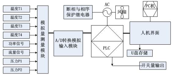
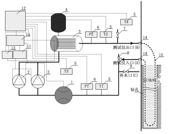
[0070] figure 1 It is a schematic diagram of the principle structure of the tester, which includes a pipeline circulation system, a test system and a monitoring system.

[0071] The pipeline circulation system is composed of flow sensor 1, circulating water pump 2, electric heater 3, expansion tank 4, exhaust valve 7, special joint 14, U-shaped buried pipe 15, three-way valve 8 and water supply valve 9, One side of the flow sensor 1 is threaded to the inlet A of the tester through a DN32 stainless steel pipe. There is a three-way valve 8 connected to this section of the pipeline. The water supply valve 9 is connected to the C-end pipeline, and the other side of the LWGY-25 turbine flow sensor 1 is connected with the PWN-162 circulating water pump 2 through a DN32 stainless steel pipe, and the upper part of the circulating water pump 2 is connected to the rated heating power through the pipeline. The lower part of the 12KW electric heater 3 is connected by welding, and the upp...

Embodiment 2

[0081] Figure 5 For tester test flowchart, the testing process of the present invention specifically includes the following steps:

[0082] Step 1: Preparation before system initialization test.

[0083] Bury the buried pipe filled with circulating fluid in the stratum where the holes are drilled according to the design requirements. After the boreholes are backfilled, place them for 2 to 3 days to restore the ground temperature to the initial state, reduce the disturbance of the boreholes to the stratum, and ensure the measurement results accurate.

[0084] Connect the two ends of A and B of the tester circulation pipeline with the two ends of the U-shaped underground pipe 15 respectively with a special joint 14, so far a complete loop is formed.

[0085] After turning on the power, open the exhaust valve 7, the water supply valve 9, open the three-way valve 8 to the exhaust state, turn on the circulating water pump 2, adjust the speed of the water pump to adjust the flow...

Embodiment 3

[0108] The effective depth of the buried pipe is 80m. The buried pipe in the test hole is single U-shaped, and the PE100-φ25mm high-density polyethylene pipe is used. The backfill of the buried pipe is a mixed slurry of bentonite and fine sand (1:4). The borehole diameter is φ150mm, and the circulating medium in the pipe is clear water.

[0109] A, B two ends of the tester circulation pipeline of embodiment 1 are respectively connected with the two ends of the U-shaped buried pipe 15 with the PE joint with internal thread of DN32 and the PE reducing joint of DN32-DN25, wherein the variable There is hot-melt welding between the diameter joint and the U-shaped buried pipe, and between the PE joint with internal thread, and the threaded connection between the PE joint with internal thread and the tester, thus forming a complete circuit.

[0110] After turning on the power, open the exhaust valve 7 and water supply valve 9, open the three-way valve 8 to the exhaust state, select t...


PUM

PropertyMeasurementUnit
pore sizeaaaaaaaaaa
pore sizeaaaaaaaaaa

Abstract

The invention discloses an instrument for testing the stratum in-situ thermal property of a ground source heat pump and the heat exchange quantity of a buried pipe, comprising a pipeline circulating system, a testing system and a monitoring system, wherein the pipeline circulating system is a circuit which is formed by connecting a flow sensor, a circulating water pump, an electric heater, an expanding tank, an exhausting valve, a three-way valve and a water supplying valve with a U-shaped buried pipe through connectors; and the testing system comprises a flow sensor, a temperature sensor, a pressure sensor and a power sensor, which are respectively connected with the monitoring system. In the invention, the testing instrument has compact structure and is convenient for carrying; two testing modes of testing the stratum in-situ thermal property and the heat exchange quantity can be economically and conveniently realized at the same time by utilizing one machine; two circulating pumps are alternately used to prolong the service life of the circulating pumps; the test and the adjustment are more convenient; and the testing data is accurate.

Description

technical field [0001] The invention belongs to the technical field of testing the ground-source heat pump buried pipe system of the new technology of heating, ventilating and air-conditioning, and particularly relates to a tester and an on-site testing method for in-situ thermophysical properties of the formation around the underground heat exchanger and the heat transfer capacity of the buried pipe. Background technique [0002] With the promotion and application of ground source heat pump technology in our country, a large number of ground source heat pump projects have succeeded or failed. The main reason is that there is a large deviation in the design of ground source heat pumps. [0003] At present, the design of ground source heat pump mainly relies on foreign experience, but does not carry out reasonable design according to the actual domestic geological conditions, hydrological conditions and ground temperature distribution conditions. [0004] The thermal physical...

Claims


Application Information

Patent Timeline
Patent Type & Authority Applications(China)
IPC IPC(8): G01N25/20
Inventor 李晓昭车平马娟
Owner NANJING UNIV
Why Eureka
Try Eureka