Axial magnetic path multi-pole pair reluctance type rotary transformer

A rotary transformer and axial magnetic circuit technology, applied in the field of transformers, can solve the problems of air gap increase, input and output impedance reduction, etc., and achieve the effect of uniform air gap, increased impedance, and air gap

Inactive Publication Date: 2011-04-27
HARBIN INST OF TECH
View PDF4 Cites 22 Cited by
  • Summary
  • Abstract
  • Description
  • Claims
  • Application Information

AI Technical Summary

Problems solved by technology

[0004] The purpose of the present invention is to solve the problem that the air gap increases and the input and output impedance decreases when the existing reluctance rotary transformer is designed with variable reluctance, and provides an axial magnetic circuit multi-pole reluctance Resolver

Method used


Image

  • Axial magnetic path multi-pole pair reluctance type rotary transformer
  • Axial magnetic path multi-pole pair reluctance type rotary transformer
  • Axial magnetic path multi-pole pair reluctance type rotary transformer

Examples


specific Embodiment approach 1

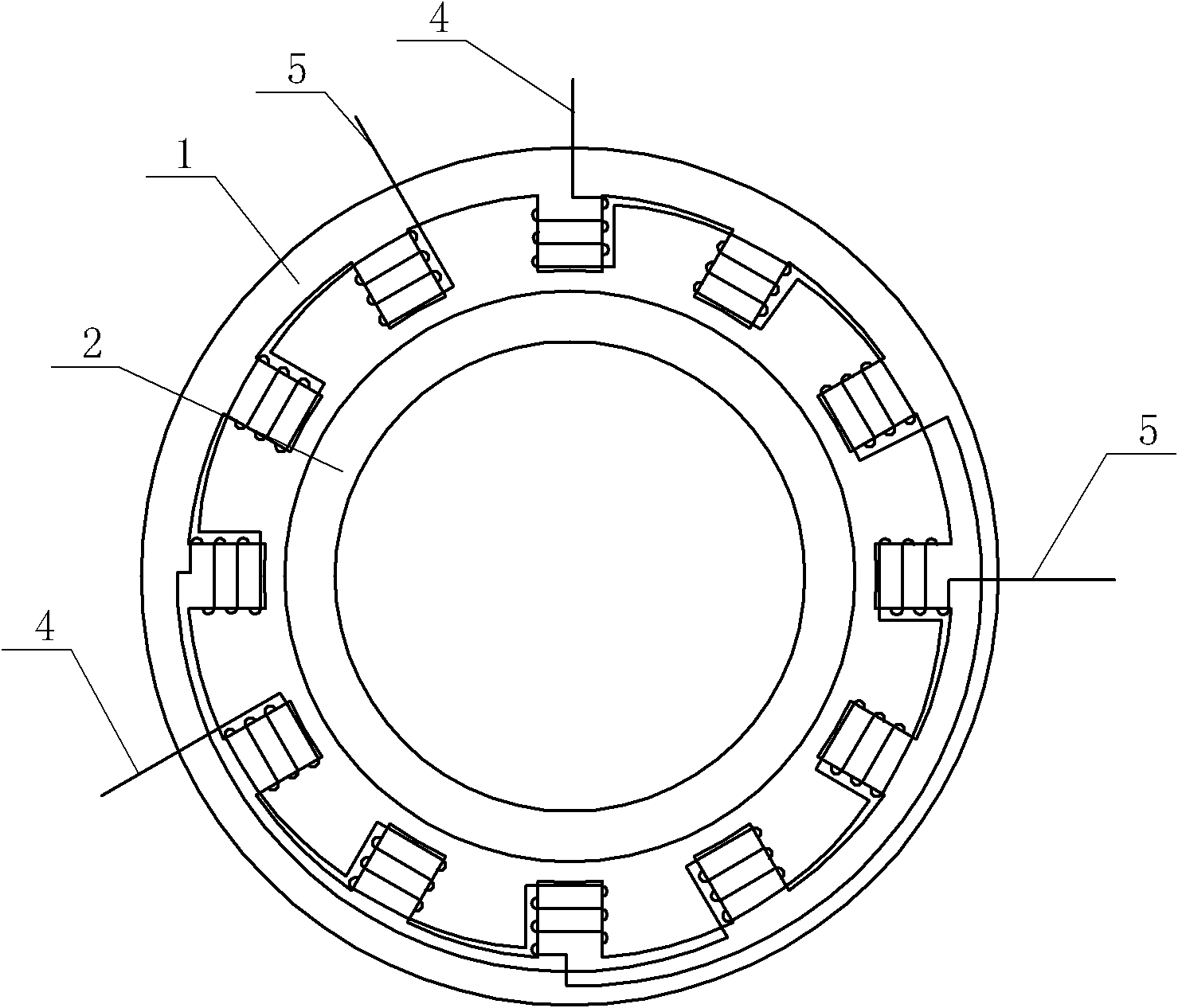
[0019] Specific implementation mode one: the following combination Figure 1 to Figure 5 This embodiment is described. This embodiment includes a stator 1 and a rotor 2. There is an air gap between the inner surface of the stator 1 and the outer surface of the rotor 2.

[0020] It also includes excitation winding 3, phase A signal winding 4 and phase B signal winding 5,

[0021] Described stator 1 is cylindrical, is made up of stator upper section 1-1, stator middle section 1-2 and stator lower section 1-3 along its axial direction, and the shape of stator upper section 1-1 and stator lower section 1-3 is identical, and stator upper section 4PN convex teeth 1-4 are evenly arranged along the circumferential direction on the inner surface of the stator 1-1 and the lower section 1-3 of the stator, where P is the pole pair number, N is a natural number, and the adjacent convex teeth 1-4 are A tooth groove, the inner diameter of the tooth groove is the same as the inner diameter o...

specific Embodiment approach 2

[0028] Specific implementation mode two: the following combination Figure 4 This embodiment is described. This embodiment is a further description of Embodiment 1. The upper stator section 1-1, the middle stator section 1-2 and the lower stator section 1-3 are all iron cores formed by laminating annular silicon steel sheets. Other components and connections are the same as those in Embodiment 1.

specific Embodiment approach 3

[0029] Embodiment 3: This embodiment is a further description of Embodiment 1 or 2. The number of turns of the A-phase signal winding 4 and the B-phase signal winding 5 is equal. Other compositions and connections are the same as those in the first or second embodiment.

[0030] working principle:

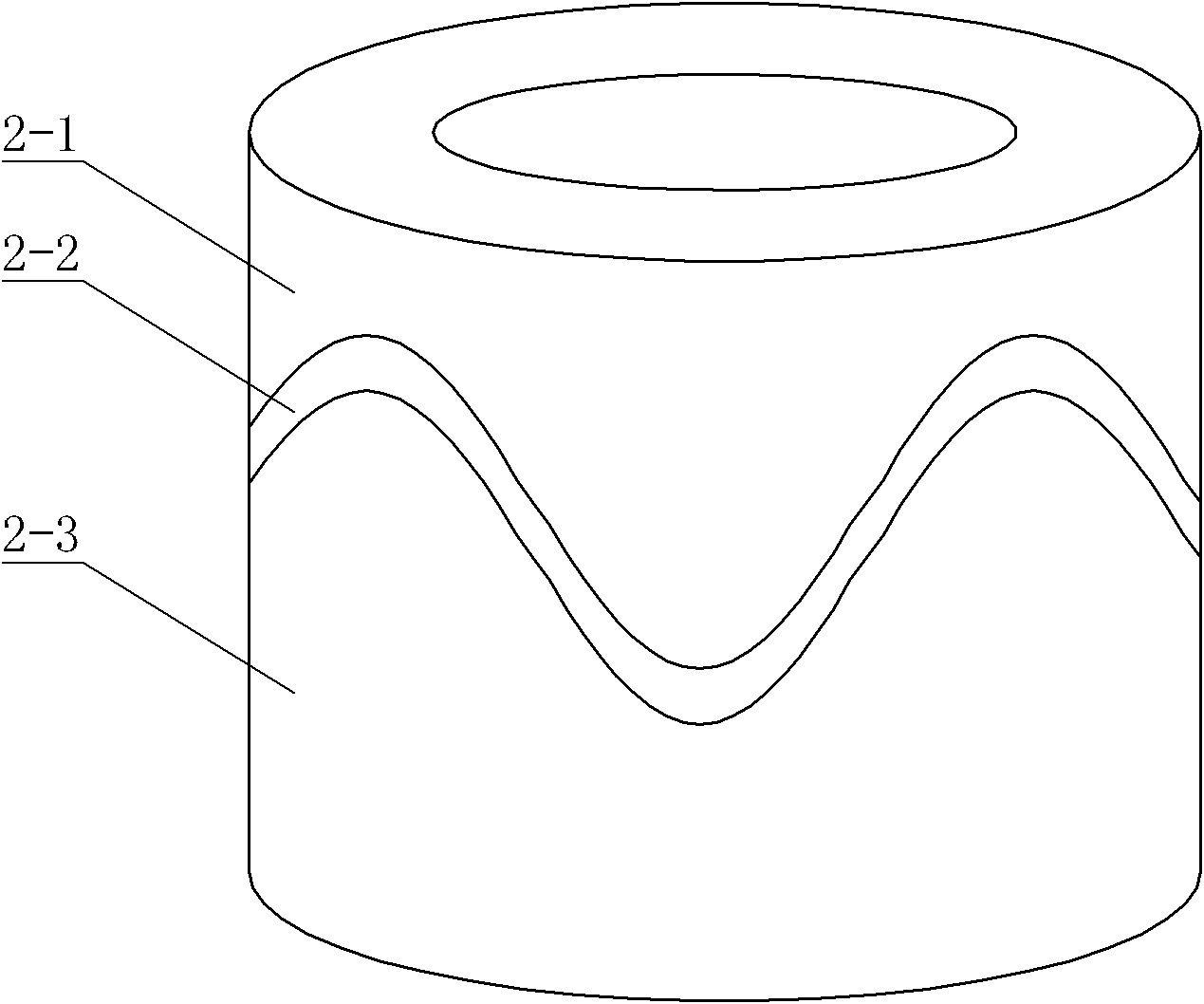
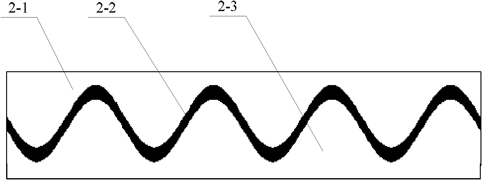
[0031] In the present invention, the coupling area between the rotor 2 and the teeth of the stator 1 is the sum of the coupling areas between the rotor 2 and the convex teeth 1-4 of the upper stator section 1-1 and the convex teeth 1-4 of the stator lower section 1-3. Assuming that at a certain moment, the coupling area between the rotor 2 and the convex teeth 1-4 of the stator upper section 1-1 is S 上 , the coupling area with the protruding teeth 1-4 of the lower section 1-3 of the stator is S 下 , then the total coupling area is S=S 上 +S 下 . Since the reluctance rotary transformer of the present invention is P-polar, its mechanical cycle is equal to the electric cycle of P ti...


PUM

PropertyMeasurementUnit
lengthaaaaaaaaaa

Abstract

The invention relates to an axial magnetic path multi-pole pair reluctance type rotary transformer, belonging to the technical field of transformers. The invention solves the problems that an air gap is increased and input output impedance is reduced in the variable reluctance design of the existing reluctance type rotary transformer. An air gap is formed between a stator and a rotor, the upper section of the stator and the lower section of the stator are in the same shape, the inner circle surface is distributed with 4PN convex teeth along the peripheral direction, a tooth groove is arranged between adjacent convex teeth, and the inner diameter of the tooth groove is the same as the middle section of the stator; the middle section of the permeability material of the rotor is corrugate along the peripheral direction, and the number of peaks is P; an exciting winding is arranged in a groove which is formed on the stator inner surface at the middle section of the stator and is coaxial with the stator; and N adjacent convex teeth at the same positions of the upper section of the stator and the lower section of the stator form a group, A phase signal windings and B phase signal windings are alternately arranged on 4P groups of convex teeth, homopolar in-phase signal windings are wound on the same group of convex teeth, and homopolar in-phase homopolar signal windings are connected in forward series. The invention is used for measuring speed and position of a servo system.

Description

technical field [0001] The invention relates to an axial magnetic circuit multi-pair reluctance rotary transformer, which belongs to the technical field of transformers. Background technique [0002] The multi-pole resolver is a high-precision position testing element, and the complementarity of its magnetic circuit structure can offset the measurement error caused by factors such as eccentricity. Traditional wire-wound resolver, since its input winding and output winding are placed on the rotor and stator respectively, in order to realize the brushless resolver, it is necessary to add a coupling transformer, which complicates the structure of the resolver; One is a vernier type rotary transformer, whose input winding and output winding are both arranged on the stator to realize brushless, but this rotary transformer needs to adopt a sinusoidal winding with complex structure. [0003] At present, the rapidly developing reluctance rotary transformer fundamentally solves the ...

Claims


Application Information

Patent Timeline
Patent Type & Authority Applications(China)
IPC IPC(8): H01F38/18H02K15/02H02K1/02H01F27/28
Inventor 尚静徐谦李庆辉刘承军胡建辉徐永向
Owner HARBIN INST OF TECH
Why Eureka
Try Eureka