Axial magnetic path multi-pole pair reluctance type rotary transformer
A rotary transformer and axial magnetic circuit technology, applied in the field of transformers, can solve the problems of reduced input and output impedance, increased air gap, etc., to achieve the effect of increased impedance, uniform air gap, and small air gap
- Summary
- Abstract
- Description
- Claims
- Application Information
AI Technical Summary
Problems solved by technology
Method used
Image
Examples
specific Embodiment approach 1
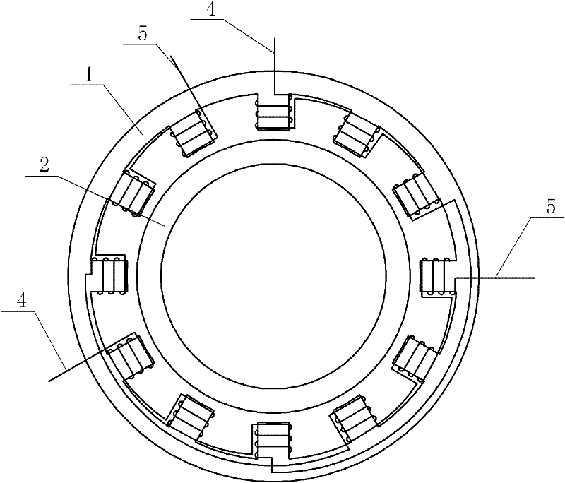
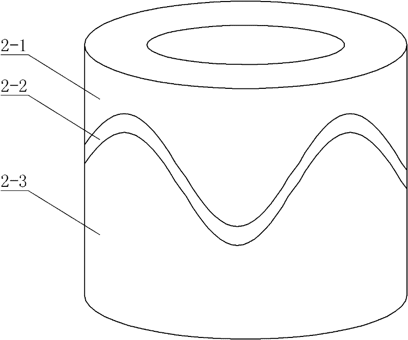
[0019] Specific implementation mode one: the following combination Figure 1 to Figure 5 This embodiment is described. This embodiment includes a stator 1 and a rotor 2. There is an air gap between the inner surface of the stator 1 and the outer surface of the rotor 2.
[0020] It also includes excitation winding 3, phase A signal winding 4 and phase B signal winding 5,
[0021] Described stator 1 is cylindrical, is made up of stator upper section 1-1, stator middle section 1-2 and stator lower section 1-3 along its axial direction, and the shape of stator upper section 1-1 and stator lower section 1-3 is identical, and stator upper section 4PN convex teeth 1-4 are evenly arranged along the circumferential direction on the inner surface of the stator 1-1 and the lower section 1-3 of the stator, where P is the pole pair number, N is a natural number, and the adjacent convex teeth 1-4 are A tooth groove, the inner diameter of the tooth groove is the same as the inner diameter o...
specific Embodiment approach 2
[0028] Specific implementation mode two: the following combination Figure 4 This embodiment is described. This embodiment is a further description of Embodiment 1. The upper stator section 1-1, the middle stator section 1-2 and the lower stator section 1-3 are all iron cores formed by laminating annular silicon steel sheets. Other components and connections are the same as those in Embodiment 1.
specific Embodiment approach 3
[0029] Embodiment 3: This embodiment is a further description of Embodiment 1 or 2. The number of turns of the A-phase signal winding 4 and the B-phase signal winding 5 is equal. Other compositions and connections are the same as those in the first or second embodiment.
[0030] working principle:
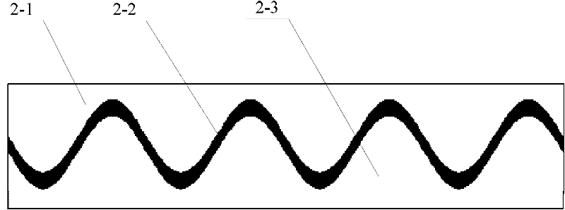
[0031] In the present invention, the coupling area between the rotor 2 and the teeth of the stator 1 is the sum of the coupling areas between the rotor 2 and the convex teeth 1-4 of the upper stator section 1-1 and the convex teeth 1-4 of the stator lower section 1-3. Assuming that at a certain moment, the coupling area between the rotor 2 and the convex teeth 1-4 of the upper stator section 1-1 is S, and the coupling area with the convex teeth 1-4 of the lower section 1-3 of the stator is S, then the total coupling area For S=S up+S down. Since the reluctance rotary transformer of the present invention is P-polar, its mechanical cycle is equal to the electric cycle of P times ti...
PUM
| Property | Measurement | Unit |
|---|---|---|
| length | aaaaa | aaaaa |
Abstract
Description
Claims
Application Information
 - R&D
- Intellectual Property
- Life Sciences
- Materials
- Tech Scout
- Unparalleled Data Quality
- Higher Quality Content
- 60% Fewer Hallucinations
Browse by: Latest US Patents, China's latest patents, Technical Efficacy Thesaurus, Application Domain, Technology Topic, Popular Technical Reports.
© 2025 PatSnap. All rights reserved.Legal|Privacy policy|Modern Slavery Act Transparency Statement|Sitemap|About US| Contact US: help@patsnap.com


