Direct-acting water pressure overflow valve with damping piston

A damping piston, direct-acting technology, which is applied in the direction of the valve's fluid energy absorption device, valve lift, valve details, etc., can solve the problems of increased processing difficulty, easy polarization of the valve, poor lubricity, etc., to improve reliability and use Effects of life, reduction of flow rate and noise, and improvement of service life

Inactive Publication Date: 2011-05-04
BEIJING UNIV OF TECH
View PDF5 Cites 39 Cited by
  • Summary
  • Abstract
  • Description
  • Claims
  • Application Information

AI Technical Summary

Problems solved by technology

①Because the gasification pressure of water is much higher than that of mineral oil, when water flows at a high speed at the valve port, the local pressure of the flow field will be lower than the gasification pressure of water, and then cavitation will occur, causing the material at the valve port to be affected by gas corrosion, thereby reducing the working reliability and life of the valve; ②Due to the low viscosity and poor lubricity of water, the friction between the valve core and the valve seat and the leakage at the valve port are serious; ③The density and elastic modulus of water are higher than those of minerals. The oil is large, and the "water hammer" phenomenon is serious; ④ The radial force caused by the uneven flow of the medium at the valve port and the spring force deviating from the axis of the valve core makes the valve core polarized
⑤ The structure of the hydraulic pressure relief valve is complicated, the processing difficulty is increased, and the production cost is high
However, the valve is prone to polarization, and the resulting vibration noise and working stability still exist
Moreover, the material used in this valve is not suitable for seawater, only suitable for less corrosive media such as fresh water and seawater.

Method used


Image

  • Direct-acting water pressure overflow valve with damping piston
  • Direct-acting water pressure overflow valve with damping piston
  • Direct-acting water pressure overflow valve with damping piston

Examples


Embodiment 1

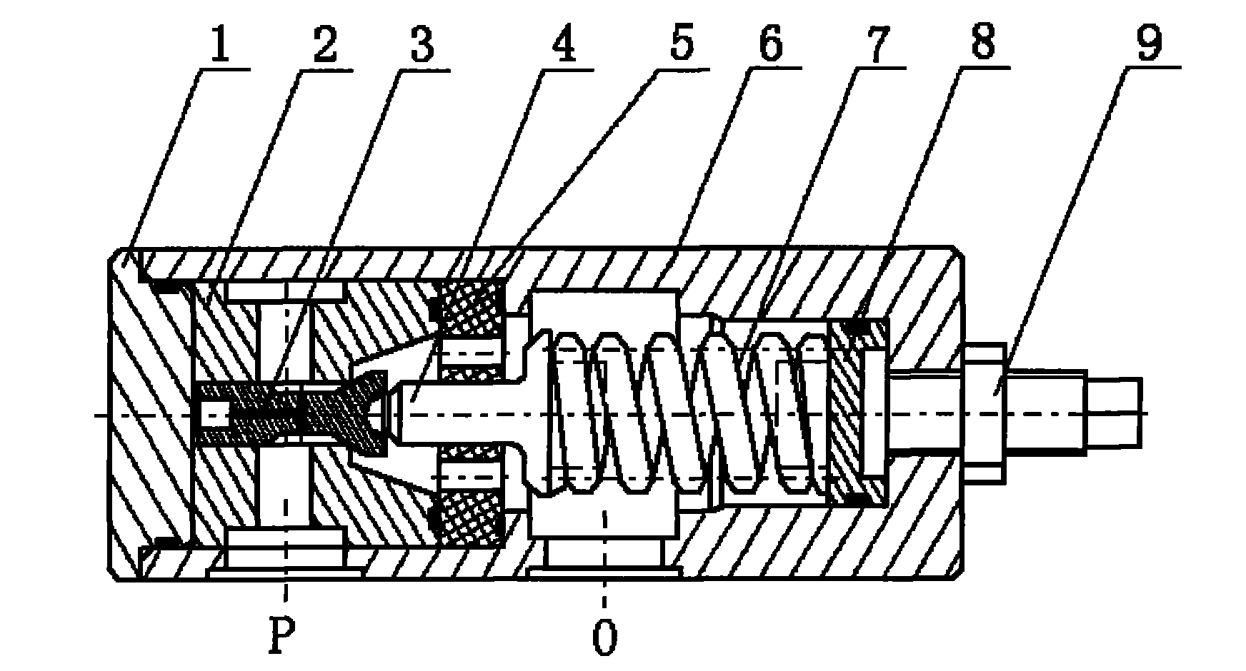
[0021] Such as figure 1 As shown, the overflow valve includes an end cover 1 and a valve seat 2, a valve core 3, a left spring seat 4, a guide sleeve 5, a spring 7, a right spring seat 8, and a pressure regulating screw 9 arranged sequentially in the valve body 6; The valve seat 2 has an annular groove in the radial direction, and a cross hole in the axial and radial direction, and a T-shaped elongated through hole in the valve core 3 in the axial and radial direction. The countersunk groove is connected, the countersunk groove and the end cover 1 form a damping chamber, the valve core 3 is inside the valve seat 2, and the cylindrical surface of its tail forms a guiding surface with the axial through hole of the valve seat 2, and the valve body formed by the valve seat 2 The mouth is a cone valve structure; the valve core 3 and the left spring seat 4 contact and cooperate to transmit the pressure regulating spring force, and the contact surface of the two is a spherical surfac...

Embodiment 2

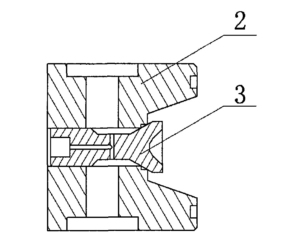
[0025] attached figure 2 It is the embodiment of the valve seat and the valve core secondary throttling valve port of the present invention. That is, when the relief valve works under a relatively high pressure state, the contact port between the valve seat 2 and the valve core 3 is designed as a countersunk groove and then the through hole is processed, so that a two-stage pressure is formed between the valve seat and the valve core. The structure of the orifice can reduce the hazards of cavitation and leakage.

Embodiment 3

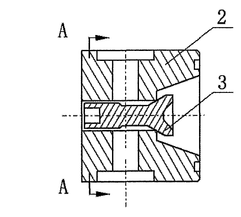
[0027] attached Figure 3-4 It is another embodiment in which the spool of the present invention acts as a damping piston. That is, there is no need to open T-shaped through holes along its radial and axial directions, and the outer cylindrical surface of the tail end of the valve core 3 is milled and flattened, so that the high-pressure water at the water inlet directly enters from here and acts on the bottom of the piston. On the one hand, it plays a damping role when the poppet valve is opened or closed, which is used to improve the stability of the poppet valve; on the other hand, it is used to ensure that the poppet valve will not tilt after opening, so as to improve the static characteristics of the poppet valve.


PUM


Abstract

The invention relates to a direct-acting water pressure overflow valve with a damping piston. The overflow valve comprises an end cover, as well as a valve seat, a valve core, a left spring seat, a guide sleeve, a spring, a right spring seat and a pressure regulating screw which are arranged in a valve body sequentially; an annular groove and a cross through hole are arranged in the valve seat, the valve core is arranged in an axial through hole of the valve seat, the end part of the valve core is provided with a countersunk groove, a cylindrical surface at the tail part of the valve core and the axial through hole of the valve seat form a guide surface, and cylindrical surface at the tail part of the valve core and a valve port formed by the valve seat form a cone valve structure; the valve core is in contact fit with the left spring seat; the left spring seat is guided by the inner bore of the guide sleeve, the guide sleeve is provided with a small through-flow hole, and the right side of the guide sleeve is provided with the annular groove; the spring is positioned between the left spring seat and the right spring seat; and the pressure regulating screw is connected with the valve body by screw threads. The overflow valve is suitable for a pressure control element in a medium and high-pressure water hydraulic system using seawater, fresh water, a high water base or the like as a working medium. Compared with similar valves, the overflow valve has the advantages of simple structure, convenience for processing, low leakage, small vibration, low noise, good cavitation corrosion resistance and high working stability.

Description

technical field [0001] The invention relates to a pressure control element in a water hydraulic system, in particular to a direct-acting hydraulic overflow valve with a damping piston, which belongs to the valve category and is suitable for medium and high pressures with seawater, fresh water, seawater base, etc. as working media. Pressure control elements in water hydraulic systems. Background technique [0002] Relief valve is a commonly used pressure control component in hydraulic system, which can be used as constant pressure relief valve or safety valve. Oil is often used as the working medium in the hydraulic system, and when the overflow valve is used in water (including seawater, fresh water or high water base, etc.) medium, a series of technical problems will arise. ①Because the gasification pressure of water is much higher than that of mineral oil, when water flows at a high speed at the valve port, the local pressure of the flow field will be lower than the gasif...

Claims


Application Information

Patent Timeline
Patent Type & Authority Applications(China)
IPC IPC(8): F16K17/06F16K47/02F16K47/04F16K1/38
Inventor 聂松林温建东阮俊喻国哲尹方龙
Owner BEIJING UNIV OF TECH
Why Eureka
Try Eureka