Cooling roller

A technology of cooling roll and cooling medium, applied in the field of amorphous strip manufacturing equipment, can solve the problems of shortening the life of the cooling roll, slowing down the water flow speed, and large water flow resistance, so as to improve the cooling capacity, reduce the production process, and prevent the stagnant state. Effect

Inactive Publication Date: 2011-05-11
滨州益谦非晶金属材料科技有限公司
View PDF14 Cites 6 Cited by
  • Summary
  • Abstract
  • Description
  • Claims
  • Application Information

AI Technical Summary

Problems solved by technology

But this patent technology also has the following deficiencies: first, due to the use of high-pressure water spray and internal helical structure, and the direction of rotation of the copper roller is opposite to the direction of the internal helical structure, the circulating water near the inner surface of the copper roller becomes Turbulent flow state, when the water flow is turbulent, its energy loss increases, the resistance of the water flow is large, the flow rate is small, and the speed of the water flow slows down. The heat exchange with the alloy melt is the whole of the circulating water, not the surface layer of the circulating water. In this way, Due to the slow speed of the water flow, some circulating water that has undergone heat exchange cannot flow away in time, resulting in an increase in the surface temperature of the copper roll, reducing the cooling capacity of the cooling roll, thereby affecting the performance and quality of the forged amorphous alloy
Second, in this patented technology, in order to reduce the force on the axial direction of the water jacket, the water jacket adopts a hollow structure (the material of the water jacket is generally steel, iron), but, due to the dynamic balance of the hollow structure It is difficult to pass the test. During the high-speed rotation, the centrifugal force system will be unbalanced, which will shorten the life of the cooling roller. In severe cases, it may cause destructive accidents. In the production of water jackets with hollow structures, it is often necessary to remove materials or Only by redistributing the mass can it reach a state of dynamic balance, which increases the difficulty of the manufacturing process of the water jacket and increases the production cost

Method used


Image

  • Cooling roller
  • Cooling roller
  • Cooling roller

Examples


Embodiment Construction

[0031] In order to make the content of the present invention more clearly understood, the present invention will be further described in detail below according to the specific embodiments of the present invention and in conjunction with the accompanying drawings.

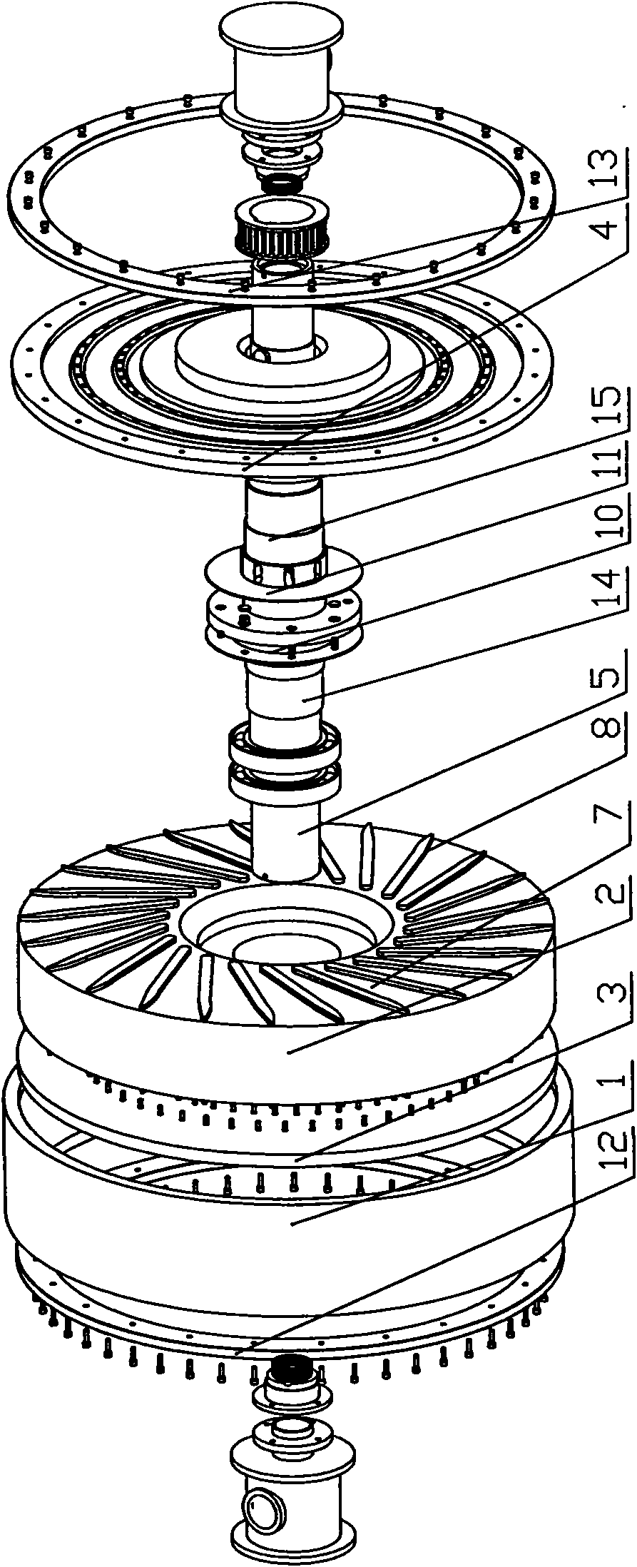
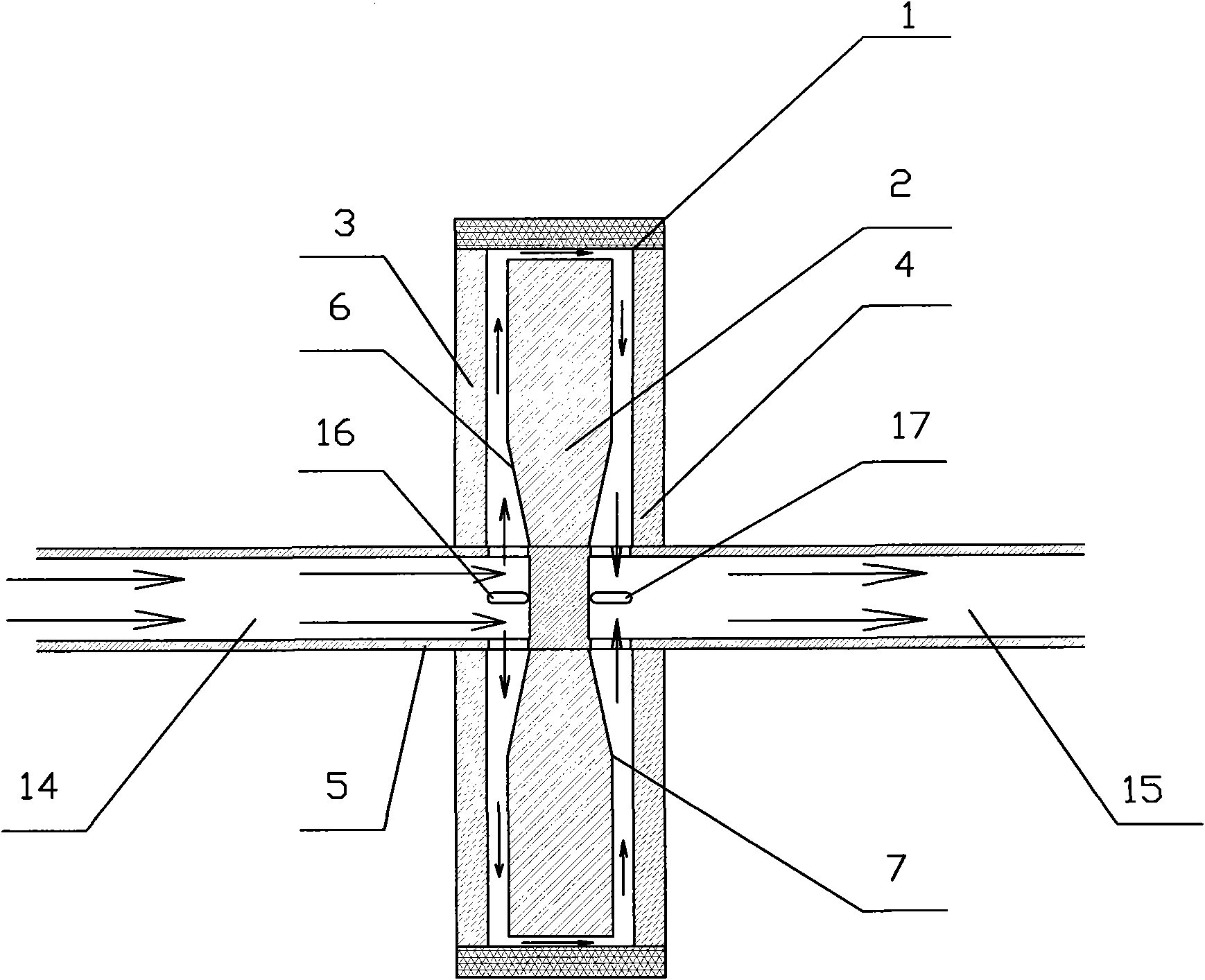
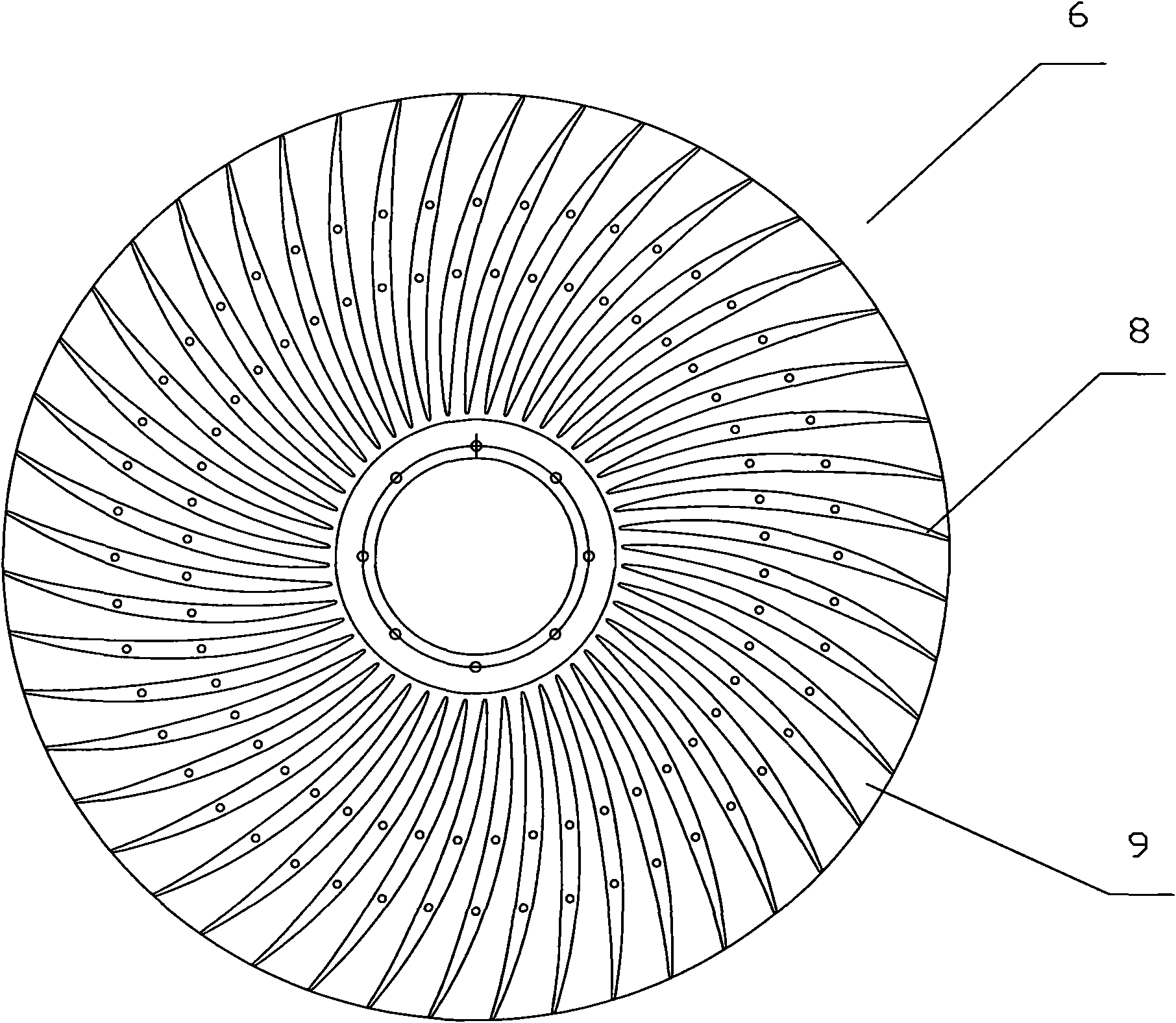
[0032] A cooling roll according to the present invention is as figure 1 , figure 2 As shown, it can be seen from the figure that the cooling roll includes a copper sleeve 1, an inner core 2 and two cover plates, the copper sleeve 1 is a hollow structure, and the two cover plates are respectively fixedly connected to the copper The open ends of the sleeve 1 cooperate with the copper sleeve 1 to form a closed cavity suitable for accommodating the inner core. The two cover plates include a left cover plate 3 and a right cover plate 4, in order to ensure the airtightness of the closed structure, a left peripheral compression flange 12 can be respectively set on the left cover plate 3 and the right cover plate 4 and t...


PUM


Abstract

The invention relates to a cooling roller, comprising a copper sleeve, an inner core and two cover plates. A gap between the copper sleeve and the inner core is less than 3mm; the inner core is a solid cylinder structure; two end surfaces of the inner core towards the cover plates are respectively a water inlet surface and a water outlet surface; a plurality of protruded ribs are respectively shaped on the water inlet surface and the water outlet surface; the ribs extend from the centre of the inner core to the periphery of the same; and a diversion groove suitable for cooling medium to pass through is formed between every two adjacent ribs. The cooling roller disclosed by the invention ensures that circulating water on the inner surface of the copper sleeve is rapidly updated and has good dynamic balance performance during high-speed rotation, therefore, the cooling capacity of the cooling roller is obviously improved.

Description

technical field [0001] The invention relates to the field of amorphous strip manufacturing equipment, in particular to a cooling roll for amorphous strip manufacturing equipment. Background technique [0002] Amorphous alloy refers to a solid alloy in a long-range disordered arrangement state due to ultra-rapid cooling and solidification, and the alloy melt has no time to arrange and crystallize in an orderly manner. The forging method of amorphous alloy usually adopts casting the alloy melt of specific composition on the continuously moving cooling roll through the nozzle, and the alloy melt solidifies rapidly on the surface of the cooling roll to form an amorphous strip, and conforms to the surface of the cooling roll. Therefore, the cooling roll is an important part of the amorphous alloy casting equipment. Its cooling capacity directly affects the performance and quality of the amorphous alloy. amorphous alloy. In the prior art, the widely used cooling roll is a coppe...

Claims


Application Information

Patent Timeline
Patent Type & Authority Applications(China)
IPC IPC(8): B22D11/06
Inventor 陈文姬黄玉攀
Owner 滨州益谦非晶金属材料科技有限公司
Why Eureka
Try Eureka