Cyclone burning method and device for reburning fuel in cyclone drum for denitration

A cyclone combustion and cyclone technology, which is applied to the combustion of block fuel and liquid fuel, the combustion of block fuel and gaseous fuel, the combustion of block fuel and powder fuel, etc., which can solve the heat release of the cyclone Reduce the threat of normal operation of the cyclone furnace, the limited degree of fuel classification, etc., and achieve the effect of solving the burnout problem, convenient implementation, and long residence time

Inactive Publication Date: 2011-05-18
XI AN JIAOTONG UNIV
View PDF4 Cites 13 Cited by
  • Summary
  • Abstract
  • Description
  • Claims
  • Application Information

AI Technical Summary

Problems solved by technology

[0004] When the reburning technology is applied to the cyclone furnace, if the design is carried out according to the conventional reburning technology idea, that is, the cyclone is used as the main combustion zone, and the reburning zone and the burnout zone are arranged at a certain position along the height of the main furnace behind the furnace, it is bound to be possible It will have a relatively large negative impact, and even pose a threat to the normal operation of the cyclone furnace in severe cases
The main reason is: the cyclone furnace is a boiler with liquid slag discharge method. Compared with the normal combustion method, when the conventional reburning technology is adopted, the total heat re

Method used


Image

  • Cyclone burning method and device for reburning fuel in cyclone drum for denitration
  • Cyclone burning method and device for reburning fuel in cyclone drum for denitration

Examples


Embodiment Construction

[0018] The present invention is described in further detail below in conjunction with accompanying drawing:

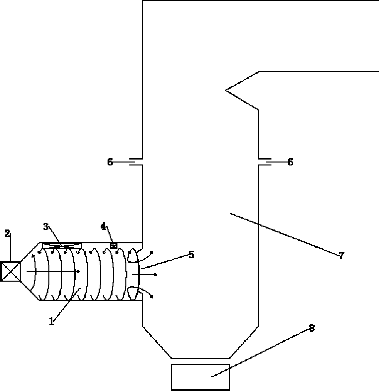
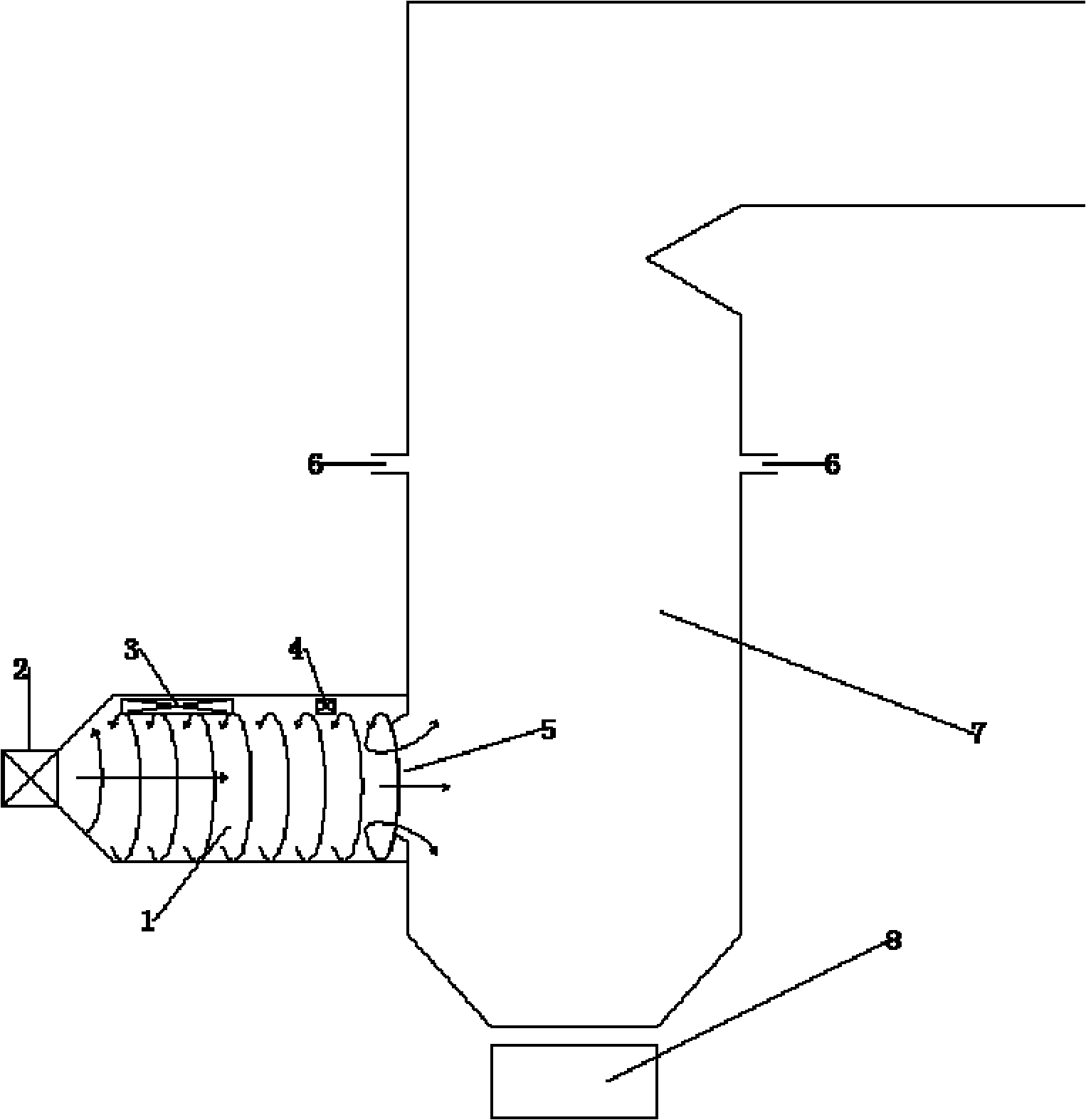
[0019] see figure 1 , a cyclone combustion method and device for achieving fuel reburning and denitrification in a cyclone proposed by the present invention, the schematic diagram of the device structure is shown in the figure. The device mainly includes cyclone, main fuel and primary air inlet, secondary air inlet, reburning fuel inlet, cyclone concave outlet, burn-out air nozzle, boiler main furnace and liquid slag granulation water tank.

[0020] The cyclone combustion method for realizing fuel reburning and denitrification in a cyclone proposed by the present invention specifically refers to: (1) the main fuel airflow sent in by the main fuel and the primary air inlet, and the high-pressure airflow sent in by the secondary air inlet The high-speed air (or "oxygen-enriched" air) is strongly mixed and combusted, forming the so-called main combustion zone in the firs...


PUM

PropertyMeasurementUnit
Particle sizeaaaaaaaaaa

Abstract

The invention discloses a cyclone reburning method and device for reburning fuel in a cyclone drum for denitration. The device comprises a cyclone drum, a boiler main hearth and a granulating water tank, wherein the cyclone drum and the boiler main hearth are connected seamlessly through a concave outlet of the cyclone drum, overfire air nozzles are distributed at the upper part of the boiler main hearth, and the granulating water tank used for granulating liquid slag is arranged at the bottom of the boiler main hearth. In the invention, since reburning denitration is realized in the cyclone drum, reburnt fuel can stay in a boiler for a longer time; meanwhile, the upper part of the boiler main hearth at the rear part of the boiler has enough space for the distribution of the overfire air nozzles; therefore, the problem that the normal operation of a cyclone furnace boiler is threatened when a conventional reburning technology is adopted is solved very well, and the problems of the reburning technology per se, such as low burn-off rate of reburnt fuel and high smoke temperature of a hearth outlet and the like, can be overcome very well. The method disclosed in the invention not only has high denitration rate, but also uses simple equipment, is convenient and easy to implement, has low cost, is easy in the reformation of a traditional boiler, has remarkable social benefit and can be promoted and applied widely.

Description

Technical field: [0001] The invention relates to a method for reducing pollutant NO in the combustion process of a cyclone furnace x Generated combustion method and device thereof. Background technique: [0002] The cyclone furnace refers to a steam boiler for power that adopts the cyclone combustion method. When the air drives the pulverized coal particles to rotate and burn in the cylinder, it is called cyclone combustion. Cyclone combustion is a stable and controllable high-speed rotating flame flow artificially organized. It fills the entire combustion chamber space and has an extremely strong disturbance ability. , It has a higher heat intensity than the general chamber combustion method. The main combustion cylinder in the cyclone furnace is called the cyclone cylinder. A cyclone furnace can have one or several cyclones. Due to the high combustion temperature (temperature above 1650°C) and extremely strong mixing intensity in the cyclone, a large amount of air poll...

Claims


Application Information

Patent Timeline
IPC IPC(8): F23C5/32F23D1/02F23K3/00F23L9/06
Inventor 车得福白文刚刘银河
Owner XI AN JIAOTONG UNIV
Why Eureka
Try Eureka