Steam turbine generator provided with axial-radial ventilating and cooling system

A turbogenerator, ventilation and cooling technology, applied in the direction of cooling/ventilation devices, electrical components, electromechanical devices, etc., can solve problems affecting the safe and stable operation of the motor, and the temperature rise of the motor, so as to reduce the heat transfer path and increase the total Effect of cooling area and increasing convective heat transfer capacity

Active Publication Date: 2011-05-18
HARBIN UNIV OF SCI & TECH
View PDF5 Cites 23 Cited by
  • Summary
  • Abstract
  • Description
  • Claims
  • Application Information

AI Technical Summary

Problems solved by technology

[0002] With the increase of the capacity of large turbo generators, the line current load of the motor increases accordingly, and the internal loss of the motor caused by the increase of the line current increases, which causes the temperature rise of the motor to be too high, which seriously affects the safe and stable operation of the motor

Method used


Image

  • Steam turbine generator provided with axial-radial ventilating and cooling system
  • Steam turbine generator provided with axial-radial ventilating and cooling system
  • Steam turbine generator provided with axial-radial ventilating and cooling system

Examples


specific Embodiment approach 1

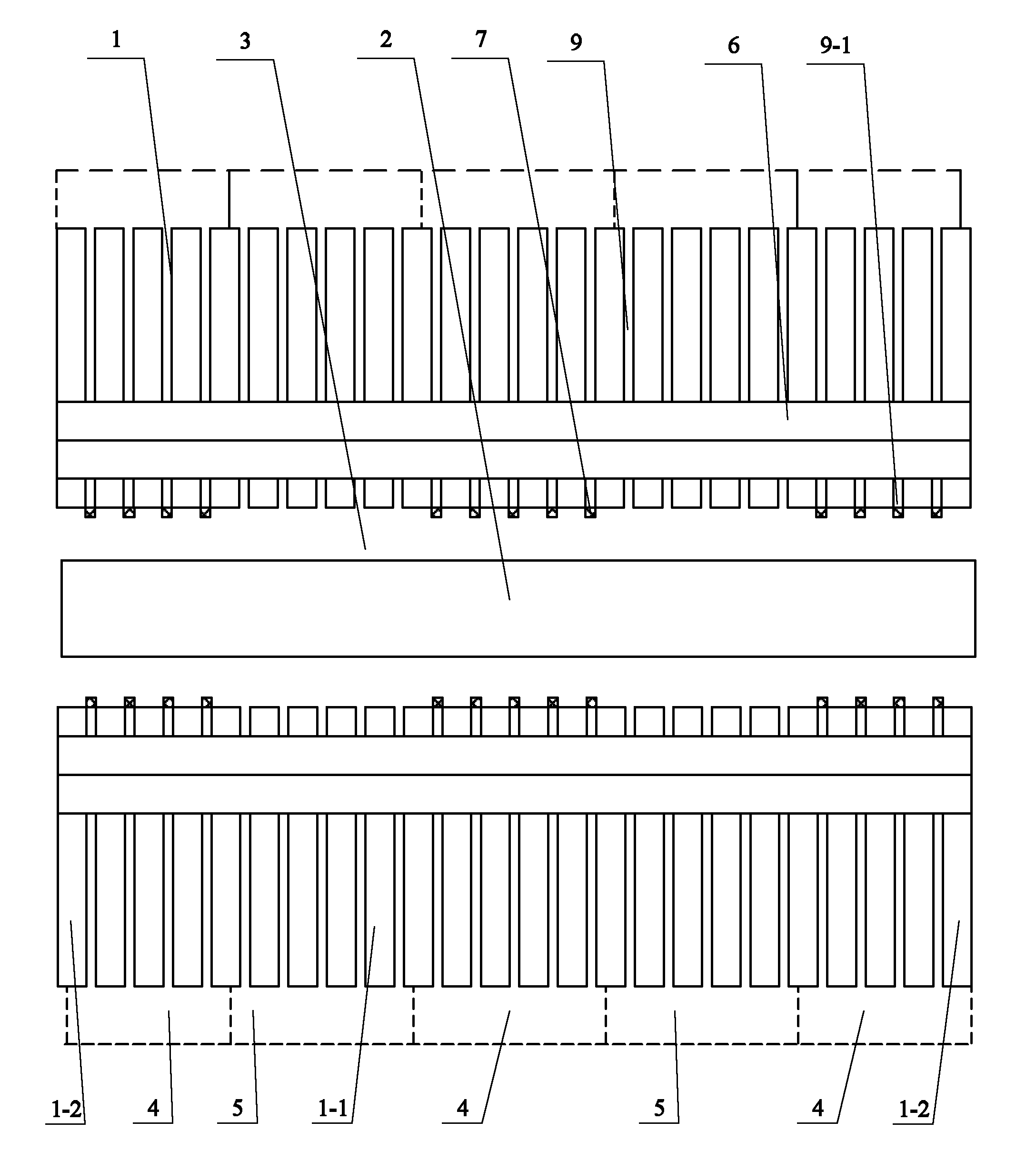
[0017] Specific implementation mode one: the following combination Figure 1 to Figure 5 This embodiment is described. This embodiment includes a stator 1 and a rotor 2. There is an air gap 3 between the inner circular surface of the stator 1 and the outer circular surface of the rotor 2. The stator 1 is composed of multi-stage stator cores arranged at equal intervals. The multi-stage The stator cores are arranged axially along the rotor 2, and the two segments of the stator cores located at both ends are the end stator cores 1-2, and the rest of the stator cores are the middle stator cores 1-1. To the ventilation ditch 9, the stator 1 is provided with a plurality of cold wind zones 4 and a plurality of hot wind zones 5 in the axial direction, the multiple cold wind zones 4 and the multiple hot wind zones 5 are arranged alternately, and the two ends of the stator 1 are In the cold wind area 4, the stator winding 6 is wound on the stator 1, and the inner surface of each stator ...

specific Embodiment approach 2

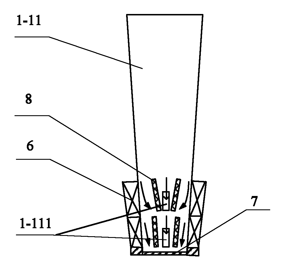
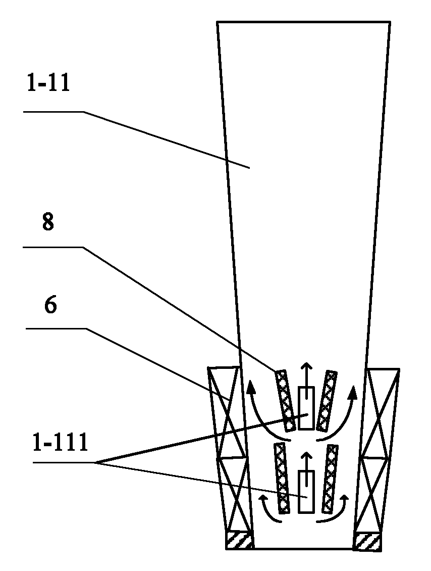
[0027] Specific implementation mode two: the following combination figure 2 and image 3 This embodiment is described. This embodiment is a further description of Embodiment 1. The axial air hole 1-111 is arranged at the center position of the stator tooth 1-11 along the circumferential direction. Others are the same as the first embodiment.

[0028] The installation positions of the axial air holes 1-111 in this embodiment can ensure the balance of heat dissipation capability.


PUM


Abstract

The invention relates to a steam turbine generator provided with an axial-radial ventilating and cooling system, which belongs to the technical field of cooling of a large air-cooling steam turbine generator and aims to improve the heat dissipation capacity of a stator winding of the large air-cooling steam turbine generator. A plurality of non magnetic-conducting distance rings are additionally provided on the basis of the ventilating and cooling system of a traditional steam turbine generator, one non magnetic-conducting distance ring is arranged at a cold air outlet of each radial ventilating duct in a cold air area to realize sealing, four sectionalized baffle plates are arranged on each stator tooth on each intermediate stator core, two axial air holes are arranged on each stator tooth on the intermediate stator core, the axial air holes axially run through along the stator teeth, the two axial air holes are arranged on each stator tooth along the radial direction, the position of each axial air hole on the stator tooth corresponds to the winding position of the stator winding, and two sides of each axial air hole are provided with two sectionalized baffle plates along the peripheral direction of a stator in a mirror symmetrical way. The steam turbine generator provided with the axial-radial ventilating and cooling system is used for cooling the steam turbine generator.

Description

technical field [0001] The invention relates to a turbogenerator with an axial radial ventilation cooling system, which belongs to the technical field of large-scale air-cooled turbogenerator cooling. Background technique [0002] With the increase of the capacity of large turbo generators, the line current load of the motor increases accordingly, and the internal loss of the motor caused by the increase of the line current increases, which causes the temperature rise of the motor to be too high, which seriously affects the safe and stable operation of the motor . Air-cooled turbogenerators are widely used in steam-gas combined cycle power plants due to their advantages of simple cooling structure, safety and reliability, low auxiliary technical requirements and short manufacturing cycle. The cooling method adopted by the air-cooled turbogenerator is indirect cooling, and its cooling effect is worse than that of direct cooling. Therefore, the heating of the stator coil beco...

Claims


Application Information

Patent Timeline
Patent Type & Authority Applications(China)
IPC IPC(8): H02K9/08H02K1/20
Inventor 李伟力管春伟薛易
Owner HARBIN UNIV OF SCI & TECH
Why Eureka
Try Eureka