Natural gas separation device

A separation device, natural gas technology, applied in gas fuel, petroleum industry, fuel and other directions, can solve the problems of difficult separation of sulfides, poor separation effect, and huge investment.

Inactive Publication Date: 2011-05-25
CHONGQING UNIVERSITY OF SCIENCE AND TECHNOLOGY
View PDF3 Cites 22 Cited by
  • Summary
  • Abstract
  • Description
  • Claims
  • Application Information

AI Technical Summary

Problems solved by technology

According to the existing molecular sieve dehydration and solution method desulfurization and decarburization process for pre-treatment, the required equipment not only requires a huge investment, but also has a huge size, cumbersome process, and relatively low input and output.
[0005] There is also a separation device that mainly uses a cyclone separator to cool and separate by relying on the ambient temperature. Although the structure is simple and the cost is low, the separation device is seriously affected by the environment. When the ambient temperature is high, the separation device is harmful to water vapor and hydrocarbons The separation of species is not complete, and it is even more difficult to separate sulfides. Generally speaking, the separation effect is not good.

Method used


Image

  • Natural gas separation device
  • Natural gas separation device

Examples


Embodiment Construction

[0019] The embodiment of the present invention discloses a natural gas separation device. The natural gas separation device can effectively separate water vapor in natural gas before liquefying natural gas, especially impurities such as sulfur and carbon. The device not only has a simple structure and low cost, but also has Good separation effect.

[0020] In order to enable those skilled in the art to better understand the technical solution of the present invention, the technical solution provided by the present invention will be further described in detail below in conjunction with the drawings and specific embodiments.

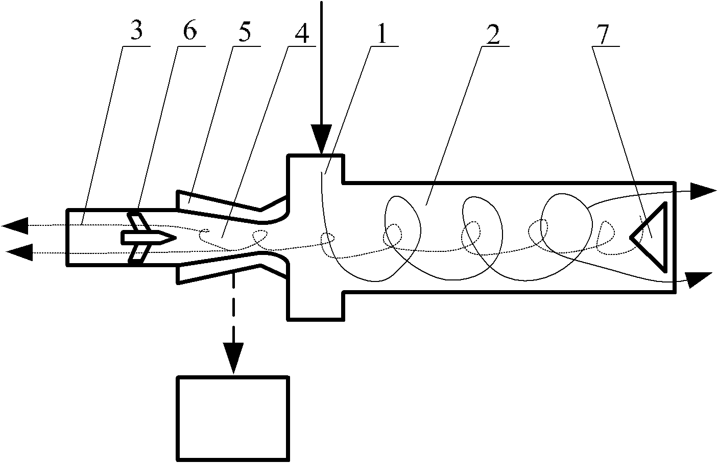
[0021] Please refer to figure 1 , figure 1 Schematic diagram of the structure of the natural gas separation device provided by the present invention.

[0022] The natural gas separation device provided by the present invention comprises a vortex tube 1, a hot end tube 2 and a cold end tube 3, the air inlet of the hot end tube 2 communicates with the hot ...


PUM


Abstract

The invention discloses a natural gas separation device. The natural gas separation device comprises a vortex tube, a hot end pipe and a cold end pipe, wherein the gas inlet of the hot end pipe is communicated with the hot gas oulet of the vortex tube; and the natural gas separation device also comprises a Laval nozzle, and the both ends of the Laval nozzle are separately communicated with the cold gas oulet of the vortex tube and the gas inlet of the cold end pipe. When the air flow in the hot end pipe reaches the Laval nozzle, as the nozzle area is reduced, the pressure of the air flow is increased, the flow rate is increased and the air flow can be in a sonic state when reaching the nozzle throat; then with the increasement of the nozzle area, the pressure of the air flow is reduced and gas expands continuously to form sonic air flow, the temperature is reduced rapidly; duing the temperature reduction process of gas, the impurity components such as CO2 and sulfide in the gas are condensated; and the condensated impurity components are thrown to the wall of the nozzle under the centrifugal force of the vortex tube to realize separation. The device of the invention has simple structure, low cost and good separation effect.

Description

technical field [0001] The invention relates to the technical field of gas-liquid separation, in particular to a natural gas separation device for natural gas purification. Background technique [0002] At present, natural gas has become an important part of the world's energy consumption, and it, together with coal and oil, is called the three pillars of world energy. Since natural gas exists in a gaseous state, the transportation and deployment of natural gas are very difficult; therefore, natural gas is generally liquefied first. For some remote small gas fields and natural gas formed from the residual gas of oil wells, liquefaction is almost the only way to utilize them. [0003] Natural gas collected from natural gas wells and coalbed methane wells and roughly separated contains a certain amount of impurity components such as water vapor, carbon dioxide, sulfide and hydrocarbons. These impurity components must be recovered and purified before natural gas liquefaction,...

Claims


Application Information

Patent Timeline
Patent Type & Authority Applications(China)
IPC IPC(8): C10L3/10
Inventor 孔松涛赵丽君蔡萍刘娟王堃
Owner CHONGQING UNIVERSITY OF SCIENCE AND TECHNOLOGY
Why Eureka
Try Eureka