Columnar coupling compound sucker rod centralizer

A sucker rod and composite technology, which is applied in the direction of drill pipe, drilling equipment, earthwork drilling and production, etc., can solve the problems of limited improvement of lubrication effect, difficulty in large-scale promotion, increase of surface cracks, etc., to achieve reasonable ratio and reduce cost , Lubrication performance improvement effect

Inactive Publication Date: 2011-05-25
黄锦滨 +1
View PDF4 Cites 10 Cited by
  • Summary
  • Abstract
  • Description
  • Claims
  • Application Information

AI Technical Summary

Problems solved by technology

Adding more metal solid lubricants such as Ag or Cu alone is difficult to promote on a large scale due to problems such as smelting and cost, and the improvement of the lubrication effect is limited; although non-metallic solid lubricants such as gra...

Method used


Image

  • Columnar coupling compound sucker rod centralizer
  • Columnar coupling compound sucker rod centralizer
  • Columnar coupling compound sucker rod centralizer

Examples


Embodiment 1

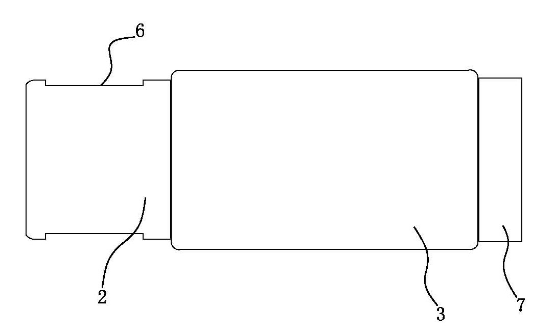
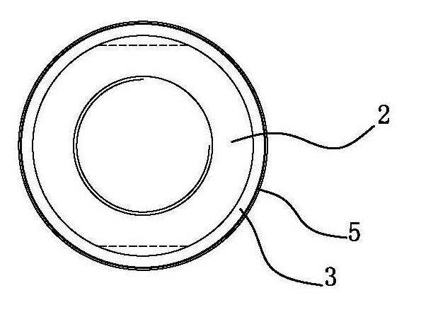
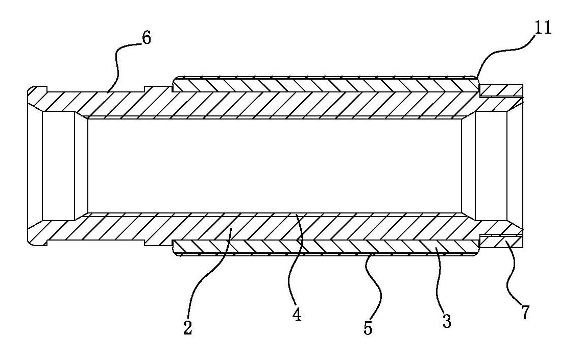
[0040] Embodiment one, see figure 1 , figure 2 , image 3 and Figure 4 , the length of the core rod 2 is 100mm, which is basically the same as that of a common coupling. The outer diameter of one end 8 of the wrench square neck 6 is basically the same as the outer diameter of the same specification coupling, and the outer diameter of the middle part 9 is less than that of the wrench square neck 6. The outer diameter of one end 8 is 2 mm, which is 1 mm higher than the outer diameter of the end 10 where the fixed collar 7 is located. The sliding sleeve 3 is a hollow cylinder, the outer diameter of which is about 4mm larger than that of the coupling with the same diameter specification, and there is a gap of 0.02mm between the inner hole and the center of the core rod, so that it can rotate freely. The surface of the sliding sleeve 3 A layer of wear-resistant and corrosion-resistant self-lubricating alloy coating 5 is prepared, with a thickness of 0.1 mm. The connection par...

Embodiment 2

[0043] Embodiment two, see figure 1 , figure 2 , image 3 and Figure 4 , The structure of this embodiment is the same as that of Embodiment 1, the difference lies in the difference in size, the fixing method of the collar 7 and the composition of the coating. The specific structure of this embodiment is as follows: the length of the core rod 2 is 130 mm, which is basically the same as that of an ordinary coupling; The diameter is less than the outer diameter 4mm of an end 8 where the square neck of the wrench is located, and is 2mm higher than the outer diameter of an end 10 where the fixed collar 7 is located. The sliding sleeve 3 is a hollow cylinder, the outer diameter of which is about 10 mm larger than that of the coupling of the same diameter specification, and there is a gap of 0.10 mm between the inner hole and the center of the core rod 2, so that it can rotate freely. A layer of wear-resistant and corrosion-resistant self-lubricating alloy coating 5 is prepared...

Embodiment 3

[0046] Embodiment three, see Figure 4 and Figure 5 , the length of the core rod 2 is 110 mm, which is basically the same as that of a common coupling. The outer diameter of one end 8 where the wrench square neck 6 is located is basically the same as the outer diameter of the coupling of the same specification, and the outer diameter of the middle part 9 is less than that of the wrench square neck. One end 8 has an outer diameter of 3 mm, which is 1.6 mm higher than the outer diameter of one end 10 where the fixed collar is located. see Figure 5 , the sliding sleeve 3 is a multi-section structure, and each section is separated from each other. The design of the multi-section structure can ensure that the other sections of the sliding sleeve 3 can rotate freely even when a single-section sliding sleeve is sand-stuck. In this embodiment, there are 3 sections, of course, it can also be 2 sections, 4 sections, etc. The sections can be separated from each other by spacers 12 o...


PUM

PropertyMeasurementUnit
Granularityaaaaaaaaaa
Thicknessaaaaaaaaaa
Surface roughnessaaaaaaaaaa

Abstract

The invention provides a columnar coupling compound sucker rod centralizer. The centralizer comprises a core rod and a sliding sleeve, wherein the core rod is a hollow cylinder and is provided with an axial via hole in the middle; the via hole is provided with an internal thread suitable for being matched with an external thread of a sucker rod; the sliding sleeve comprises a steel body and a self-lubricating alloy coating; the self-lubricating alloy coating is formed by uniformly mixing 2-6wt% of solid lubrication particles and 94-98wt% of iron-nickel alloy powder; the solid lubrication particles are formed by uniformly mixing MoS2 and WS2; and the iron-nickel alloy powder is prepared from the following components by weight: 0.5-1.1% of carbon, 10-20% of chromium, 1.5-5.5% of silicon, 1.0-4.5% of boron, 25-55% of iron and the balance of nickel. The centralizer has the following advantages: the centralizer has excellent corrosion resistance, wear resistance and self-lubricating property; the use amount of nickel and the cost can be obviously reduced; the service life and the allowable working temperature are substantially improved; the centralizer can well centralize and protect the sucker rods for a long time; and the wear of the oil pipes is reduced.

Description

technical field [0001] The invention relates to petroleum equipment, and more specifically relates to a novel column centralizer. Background technique [0002] Pumping wells have always been the main method of oil production in oilfields at home and abroad. The sucker rod is used to transmit power to the pump to extract crude oil. Due to deep oil wells and inclined wells, the sucker rod will contact and rub against the inner wall of the tubing. Over time, it will lead to eccentric wear and breakage of the sucker rod, which will cause the oil well to fail to operate normally. In order to solve the above problem of eccentric wear of sucker rods, oilfields widely adopt the method of centralizers, that is, to avoid or reduce the eccentric wear of sucker rods by installing centralizers between two adjacent sucker rods or on the sucker rods. Since the outer diameter of the centralizer is larger than that of the sucker rod and the sucker rod coupling, it will preferentially contac...

Claims


Application Information

Patent Timeline
IPC IPC(8): E21B17/10
Inventor 李良川黄锦滨田斌刘斌付小坡
Owner 黄锦滨
Why Eureka
Try Eureka