Backlight source structure and working method thereof

A backlight, LED light source technology, applied in the field of side-in LED backlight structure, can solve the problems of increasing light loss, not using the diffusion effect of phosphor powder, and not proposing the technical route of white light backlight, so as to reduce the loss of light Effect

Inactive Publication Date: 2011-05-25
SUN YAT SEN UNIV
View PDF5 Cites 11 Cited by
  • Summary
  • Abstract
  • Description
  • Claims
  • Application Information

AI Technical Summary

Problems solved by technology

But there are the following shortcomings: First, the traditional side-type backlight is used. The ink is coated on the lower surface of the light guide plate, and the fluorescent powder is doped into the ink and coated on the lower surface of the light guide plate. Most of the yellow light is generated when the blue light is excited. It needs to b

Method used


Image

  • Backlight source structure and working method thereof
  • Backlight source structure and working method thereof
  • Backlight source structure and working method thereof

Examples


Example Embodiment

[0024] The present invention will be described in further detail below in conjunction with the accompanying drawings:

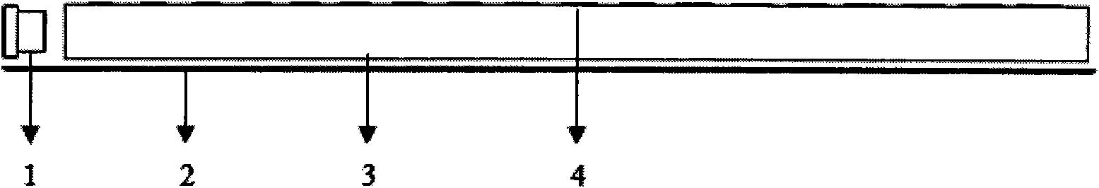
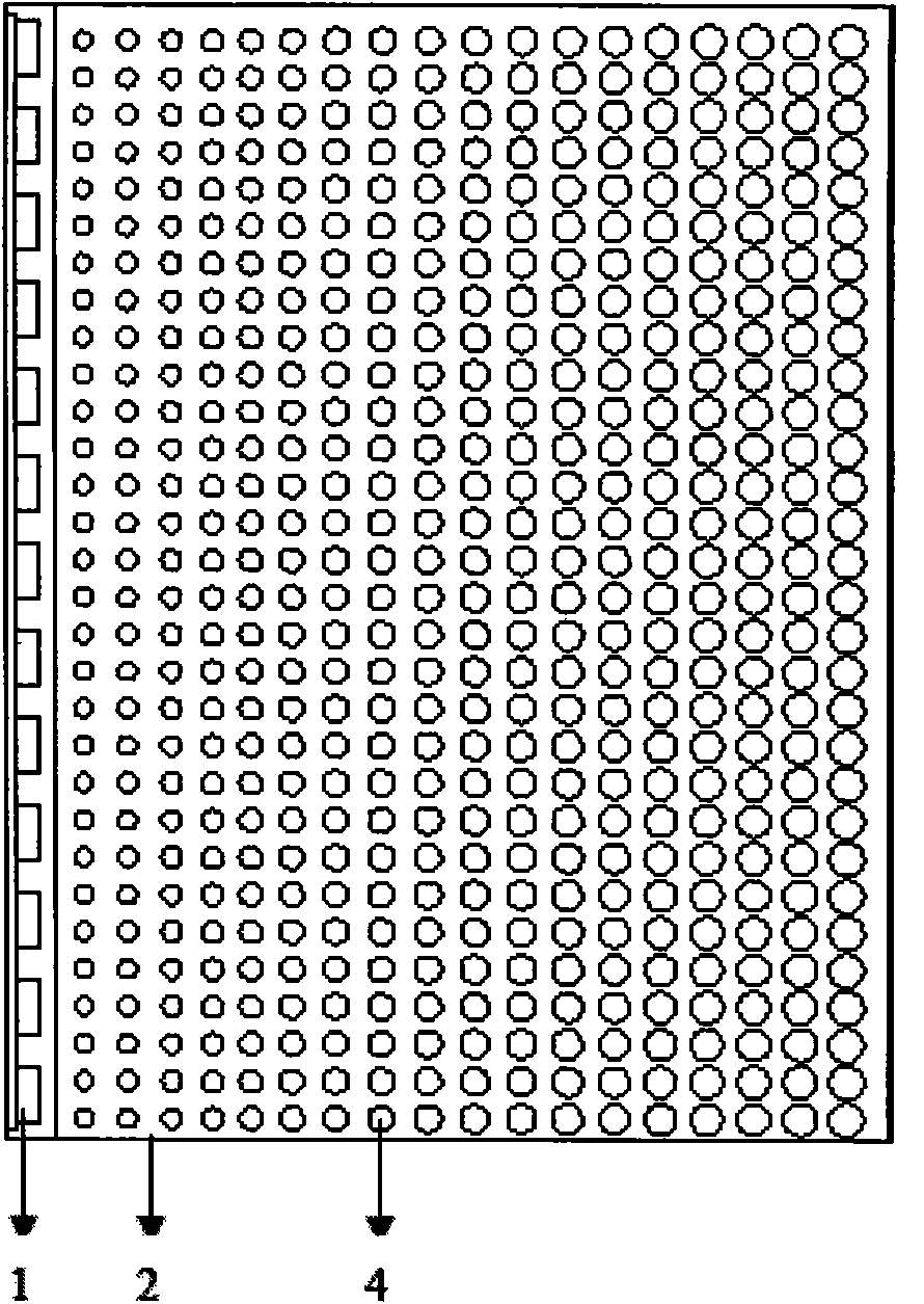
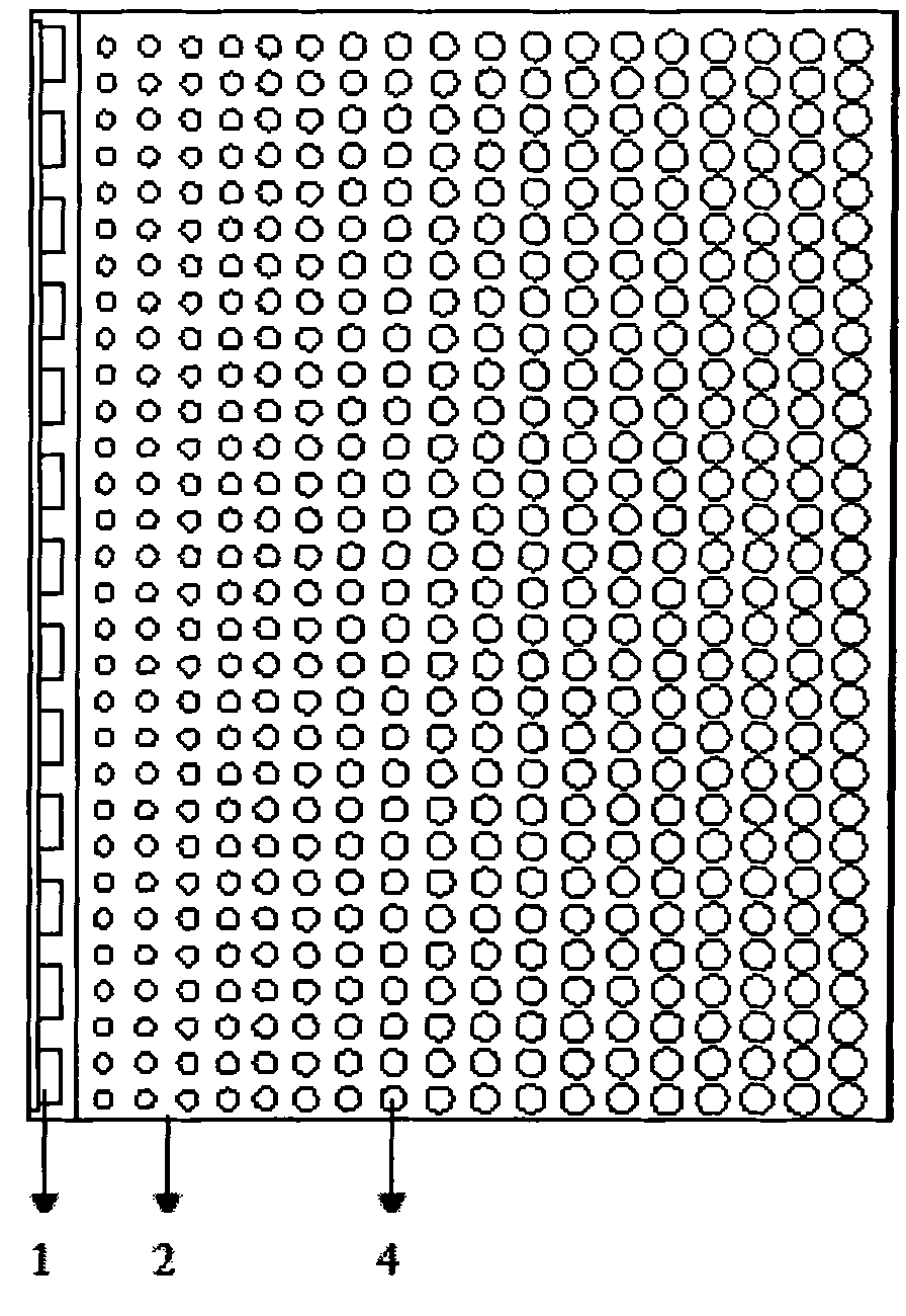
[0025] Such as figure 1 , figure 2 As shown, the blue LED light source 1 of the present invention adopts the blue LED chip to be directly packaged on the PCB aluminum substrate through the chip-on-board method, and is placed on the side of the light guide plate 3. Since the LED bare chip can be used, the light source can be made more Thin, the thickness of the PCB aluminum substrate in this example is 2mm, and the thickness of the light guide plate is 2mm. A reflective film 2 is pasted under the light guide plate 3. The light guide plate 3 is distributed with phosphor dots 4 with a diameter of 0.1 mm to 1 mm, wherein the phosphor dots 4 close to the light source have a small diameter, and the phosphor dots 4 far away from the light source have a large diameter. Above the phosphor dots 4, there are also two layers of brightness enhancing films with vertical di...


PUM


Abstract

The invention discloses a backlight source structure and a working method thereof. Emergent blue light can be mixed with long-wavelength yellow light obtained by the transformation of the blue light in the excitation of fluorescent powder to obtain required white light by adopting a rational fluorescent powder proportion and distributing fluorescent powder dots on a light guide plate according to proper rules. Compared with the conventional method in which white-light light emitting diodes (LED) form a light source, the method is convenient to operate, reduces the cost of the light source, reduces optical loss, increases the exitance of the light, can further reduce the power of a backlight source and has great significance in energy saving popularization.

Description

technical field [0001] The invention relates to the field of liquid crystal display, in particular to a novel side-in LED backlight source structure. Background technique [0002] With the continuous improvement of LED light efficiency, the market share of LED backlight is also increasing day by day. The side-in LED backlight is favored by consumers because of its ultra-thin thickness. Usually, the structure of the side-in LED backlight is that the LED light source is placed on the side of the light guide plate, and the ink is scattered through the underside of the light guide plate. The dot distribution changes the direction of light propagation, and then the diffusion film and brightness enhancement film are used to achieve the target brightness and brightness uniformity. The light sources used in this method are almost all white LEDs or their arrays that excite YAG phosphor powder with blue light to produce white light. Blue light also has loss when it is converted into ...

Claims


Application Information

Patent Timeline
IPC IPC(8): F21S8/00F21V9/10F21V8/00F21V9/40
Inventor 刘立林王钢杨建福
Owner SUN YAT SEN UNIV
Why Eureka
Try Eureka