
Optical angle measuring device and angle measuring method

An optical measurement and angle technology, applied in measurement devices, optical devices, instruments, etc., can solve the problems of high operation and debugging requirements, complex measurement system structure, easy to be affected by environmental factors, etc., to achieve simple structure and measurement accuracy. High and stable effect

Active Publication Date: 2011-05-25
SHANGHAI MICRO ELECTRONICS EQUIP (GRP) CO LTD
View PDF0 Cites 9 Cited by
  • Summary
  • Abstract
  • Description
  • Claims
  • Application Information

AI Technical Summary

Problems solved by technology

The disadvantage of the electronic level method is that the structure of the measurement system is relatively complicated, the operation and debugging requirements are high, and it is easily affected by environmental factors.

Method used


Image

  • Optical angle measuring device and angle measuring method
  • Optical angle measuring device and angle measuring method
  • Optical angle measuring device and angle measuring method

Examples


Embodiment Construction

[0029] The angle optical measuring device and angle measuring method of the present invention will be further described in detail below in conjunction with the accompanying drawings.

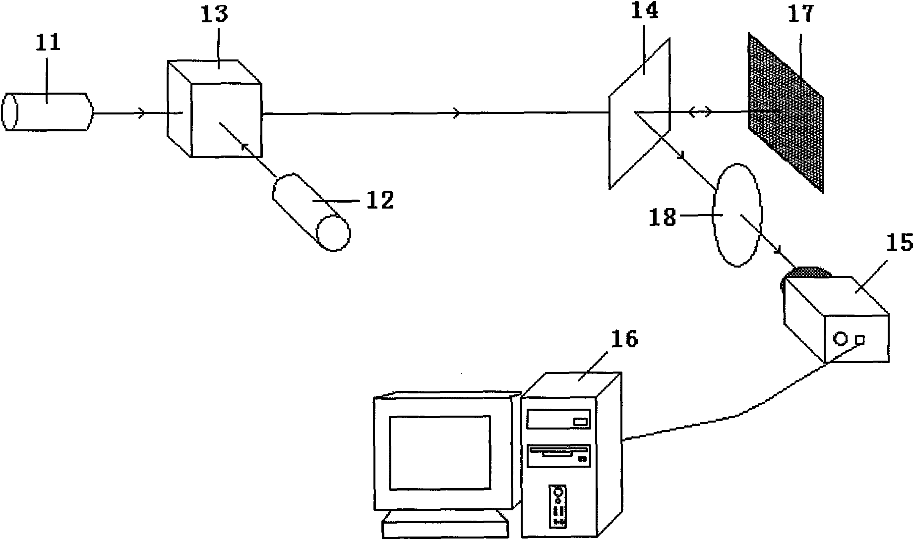
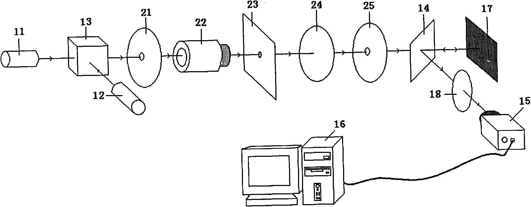
[0030] see figure 1 , the angle optical measuring device comprises two light sources 11 and 12 arranged along the optical axis of the angle optical measuring device, a dichroic prism 13, a half mirror 14, a photodetector 15, an image processor 16, a rough template installed test object ( figure 1 Only the rough template 17) and the first lens 18 installed on the measured object are shown;

[0031] The two light sources 11 and 12 are used to generate coherent light, and the light beams emitted by the two light sources 11 and 12 form a certain angle with each other; The prism 13 combines beams to generate coherent light;

[0032] The dichroic prism 13, the half-mirror 14 and the measured object are arranged in sequence; the coherent light generated by the dichroic prism 13 passes through the ha...


PUM


Abstract

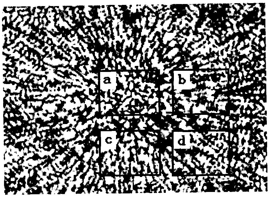
The invention provides an optical angle measuring device and an angle measuring method. The optical angle measuring device comprises two light sources, a dispersion prism, a semi-transflective mirror, a photoelectric detector, an image processor, a measured object and a first lens, wherein the two light sources are arranged along the optical axis of the optical angle measuring device; a rough sample plate is arranged on the measured object; light beams emitted by the two light sources pass through the dispersion prism and are combined into coherent light by the dispersion prism; the dispersion prism, the semi-transflective mirror and the measured object are arranged in turn; coherent light generated by the dispersion prism passes through the semi-transflective mirror and emits on the surface of the rough sample plate which is arranged on the measured object so as to be scattered; scattered light is reflected by the semi-transflective mirror and passes through the first lens in another transmission direction; scattered light focused by the first lens is acquired by the photoelectric detector on the focal plane of the first lens; and an acquired multi-dispersion speckle field light intensity distributed image is transmitted to the image processor by the photoelectric detector for image processing.

Description

technical field [0001] The invention relates to optical measurement of angles, in particular to an angle optical measurement device and an angle measurement method. Background technique [0002] In optical testing and photoelectric testing, the problem of measuring the motion of the object under test or the detector is often involved. Due to the inherent error of the mechanical stage itself and the influence of environmental factors, the actual motion of the measured object or detector includes angular changes such as yaw and pitch in addition to positional motion and vibration. In high-precision measurement, the errors caused by these angular changes cannot be tolerated. Neglect, therefore, the precise measurement of the angle plays a very important role in ensuring the accuracy of the test results. [0003] A small angle measurement method is laser interferometry, which uses the interference phenomenon of the measurement beam and the reference beam, that is, the change of...

Claims


Application Information

Patent Timeline
IPC IPC(8): G01B11/26
Inventor 池景春
Owner SHANGHAI MICRO ELECTRONICS EQUIP (GRP) CO LTD
Learn More