Improved system and method for detecting wall thickness and corrosion of well casing of gas storage well

A technology for corrosion detection and gas storage wells, applied in weather resistance/light resistance/corrosion resistance, measuring devices, instruments, etc., can solve the problems of no optical fiber sealing joint, detection interruption, too many devices, etc., to reduce the load of detection personnel, connect The effect of fast, convenient and simplified operation process

Inactive Publication Date: 2011-05-25
CHINA SPECIAL EQUIP INSPECTION & RES INST
View PDF5 Cites 17 Cited by
  • Summary
  • Abstract
  • Description
  • Claims
  • Application Information

AI Technical Summary

Problems solved by technology

[0005] 1. The downhole instruments are all submerged in water during detection, and there is no convenient and durable optical fiber sealing joint for plugging;
[0006] 2. The power supply of downhole instruments must be completed by cables, and optical cables are used to transmit signals, so there are two separate lines of optical cables and cables connected to downhole instruments in the upper part of the well. and cables, the ascent process has to be interrupted in severe cases
[0007] 3. The downhole instrument adopts the computer mode. Due to the inevitable vibration during the detection, the computer will not work normally. When the machine crashes in the middle of the detection, the entire gas storage well has to be re-tested;
[0008] 4. From the downhole to the uphole instrument, there are too many devices through which the signal is transmitted, and the failure of any one device can interrupt the detection;
[0009] 5. Optical cables need to be replaced frequently, and the cost is too high
[0010] 6. The encoder is placed in the fixed pulley part, and the encoder needs to be reinstalled every time a gas storage well is detected, and the encoder line is not armored, which is easy to damage
[0011] Due to the above reasons, the failure rate of the equipment is relatively high, and its mobility and flexibility cannot fully meet the requirements.

Method used


Image

  • Improved system and method for detecting wall thickness and corrosion of well casing of gas storage well
  • Improved system and method for detecting wall thickness and corrosion of well casing of gas storage well
  • Improved system and method for detecting wall thickness and corrosion of well casing of gas storage well

Examples


Embodiment Construction

[0044] Below in conjunction with accompanying drawing, the present invention will be further described:

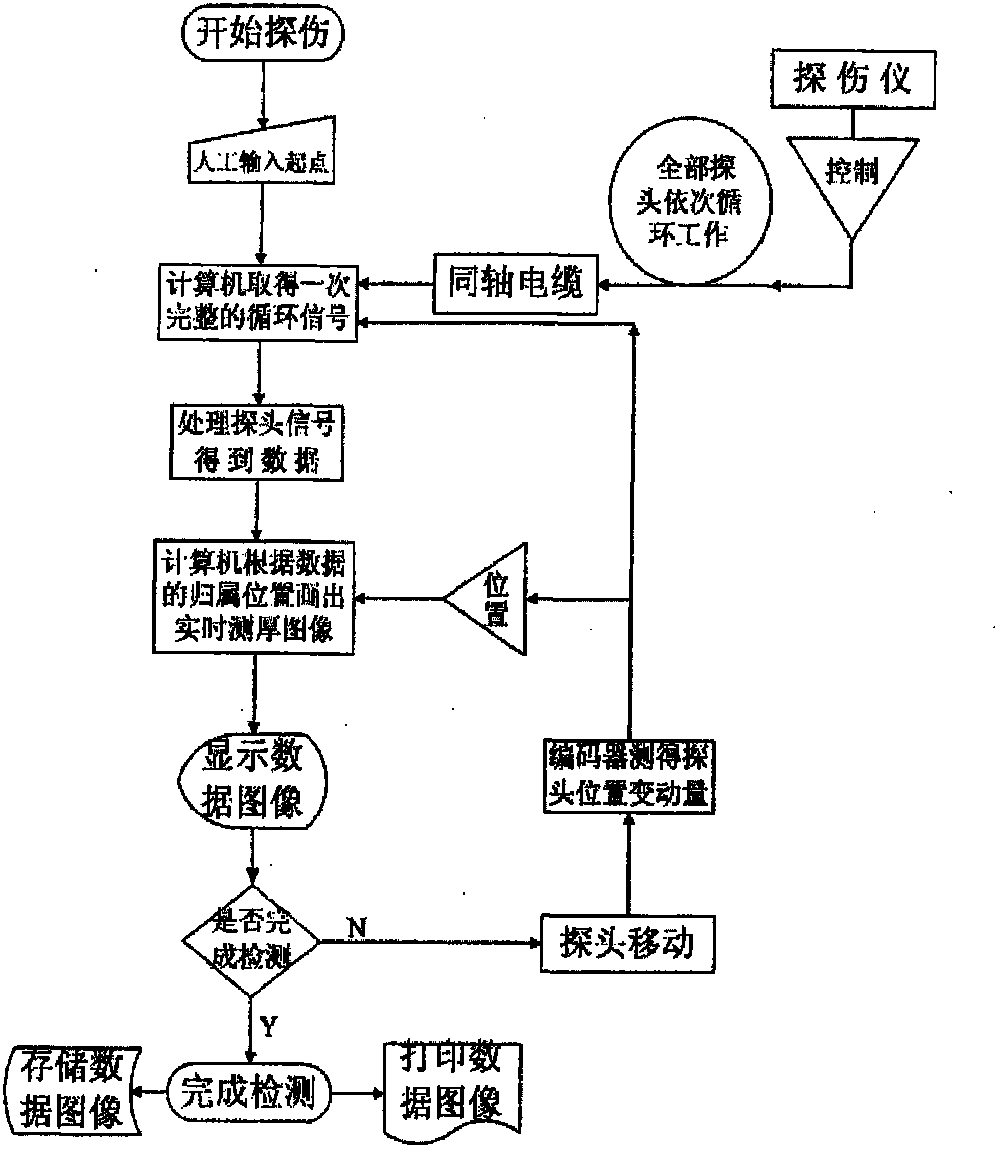
[0045] see figure 1 Shown is the flow chart of the improved wellbore wall thickness and corrosion detection method for gas storage wells.

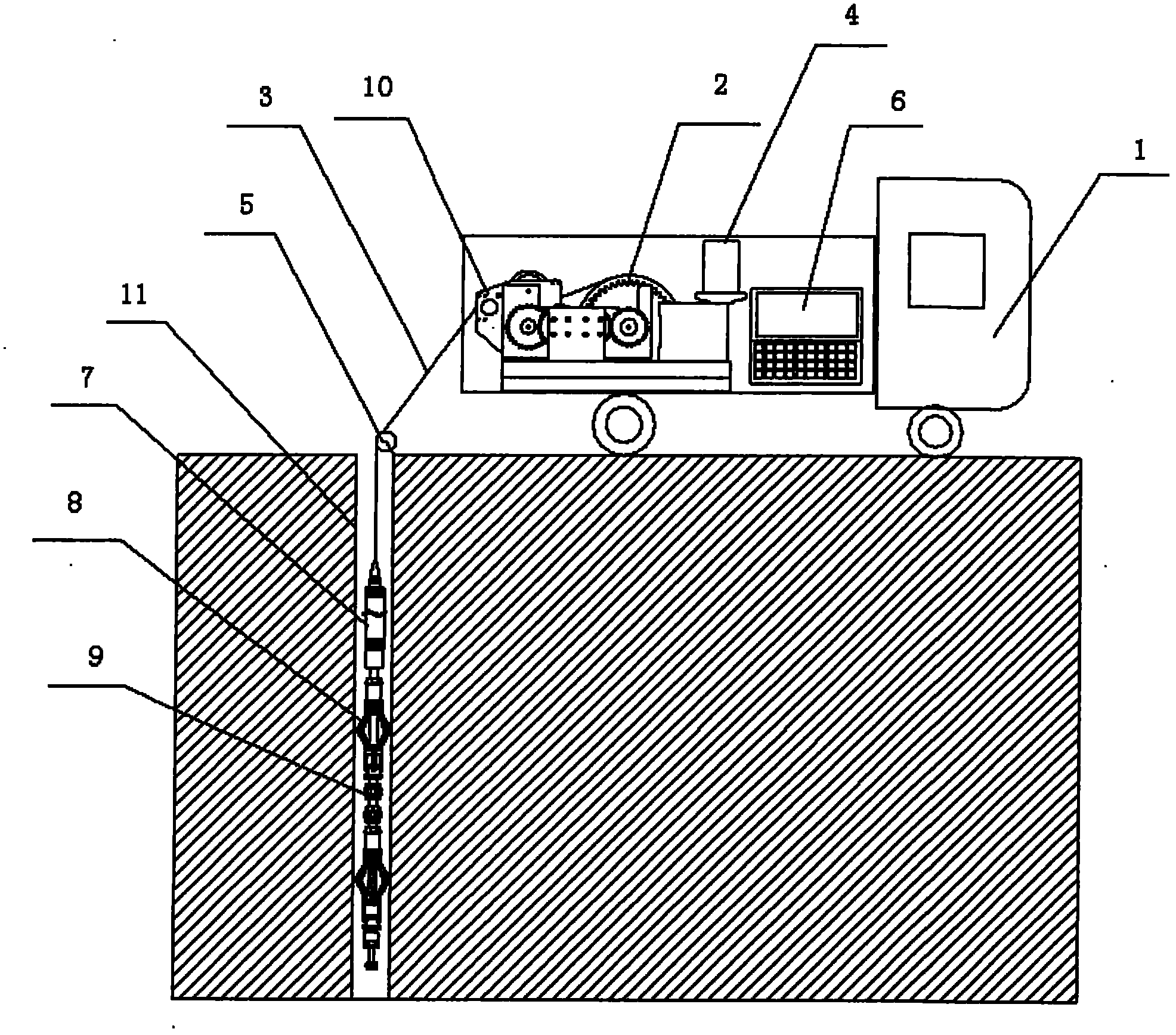
[0046] The improved detection method for wellbore wall thickness and corrosion of gas storage wells first fills the gas storage well 11 with water, installs the fixed pulley 5 at the wellhead, and the position of the mobile detection device 1 enables the armored composite wire 3 to pass through the pulley 5 and enter the storage well smoothly. Inside the gas well 11. Connect the downhole instrument with the armored composite line. In this embodiment, the mobile detection device 1 is a mobile detection system vehicle.

[0047] For the previous equipment, the improvements of the present invention include:

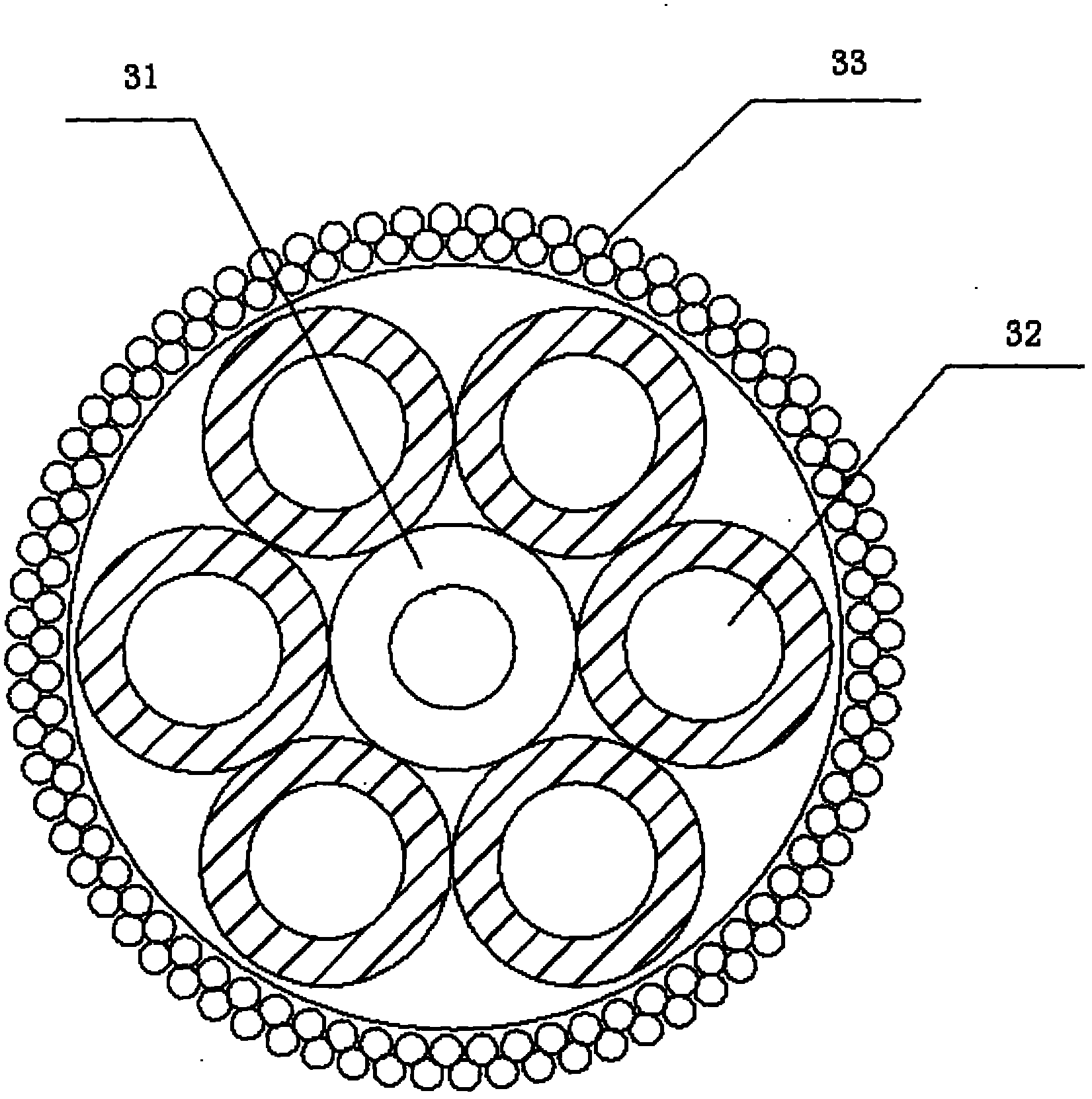
[0048]Combined with the on-site environment, the noise in the ultrasonic frequency band for detection is very small, so the optic...


PUM


Abstract

The invention discloses an improved system and method for detecting wall thickness and corrosion of a well casing of a gas storage well. The system comprises an overground signal processing part and an underground signal receiving and transmitting part arranged inside the gas storage well, wherein the overground part is provided with a mobile detection device connected with the underground part through an armored composite wire, and the detection device is provided with a dragging part and a control terminal; a coaxial cable in the armored composite wire inputs a plurality of collected analog probe signals into a computer, and the computer finishes digital conversion of analog signals and processing of data signals; the signal processing part moves up and down on the inner wall of the well casing through a centralizer; an annular water immersion analog probe array is also arranged; and the armored composite wire is manufactured by winding the coaxial cable for signal transmission with an underground instrument power cord layer by layer and winding a steel wire at the outermost layer, and the coaxial cable and the power cord share one multi-core waterproof seal joint. An encoder is directly installed at the wire swinging part in front of a roller, and the joint of encoder and the computer are in fixed connection. The system disclosed by the invention has stronger reliability and better vibration resistance, and can operate for a long time without faults.

Description

technical field [0001] Gas storage well wellbore wall thickness and corrosion detection system and method are non-destructive testing equipment specially designed for various types of gas storage wells used in gas filling stations, peak shaving stations and other related facilities to measure wall thickness and corrosion degree to evaluate their safety status and technical means. Background technique [0002] With the increasing shortage of petroleum products, the price of refined oil is getting higher and higher, and the energy problem of using gasoline as the main fuel for automobiles is becoming more and more serious. In recent years, with the deployment and implementation of the national clean energy strategy, vehicles powered by natural gas have begun to emerge in large numbers. The biggest advantage of natural gas-powered vehicles is that they are not only very low in operating costs but also environmentally friendly, so they are very popular in society. Ordinary gas...

Claims


Application Information

Patent Timeline
Patent Type & Authority Applications(China)
IPC IPC(8): G01B17/02G01N17/00
Inventor 石坤李邦宪范智勇崔高宇陈力群滕永平陈祖志段志祥韩红伟王璟陈耀华李文波段会永费学智郑雪松
Owner CHINA SPECIAL EQUIP INSPECTION & RES INST
Why Eureka
Try Eureka