Transformer structure

A transformer and winding technology, which is applied in the direction of transformers, fixed transformers, transformer/inductor casings, etc., can solve problems such as difficult to stably control the leakage inductance of transformers

Active Publication Date: 2011-05-25
DELTA ELECTRONICS INC
View PDF0 Cites 9 Cited by
  • Summary
  • Abstract
  • Description
  • Claims
  • Application Information

AI Technical Summary

Problems solved by technology

[0007] The main purpose of the present invention is to provide a transformer structure, which has a winding base with a plurality of single-slot second winding areas, through which a plurality of single-slot second winding areas are used to respectively wind a plurality of secondary windings, so as to Change the way of winding and magnetic circuit, so as to solve the problem that the air gap is formed between the primary winding and the secondary winding when the magnetic core group of the existing transformer is combined, which makes it difficult to control the leakage inductance of the transformer stably. Disadvantages such as sleeve casing around the outlet end of the secondary winding

Method used


Image

  • Transformer structure
  • Transformer structure
  • Transformer structure

Examples


Embodiment Construction

[0044] Some typical embodiments embodying the features and advantages of the present invention will be described in detail in the description in the following paragraphs. It should be understood that the present invention is capable of various changes in different forms without departing from the scope of the present invention, and that the description and drawings are illustrative in nature and not intended to limit the present invention.

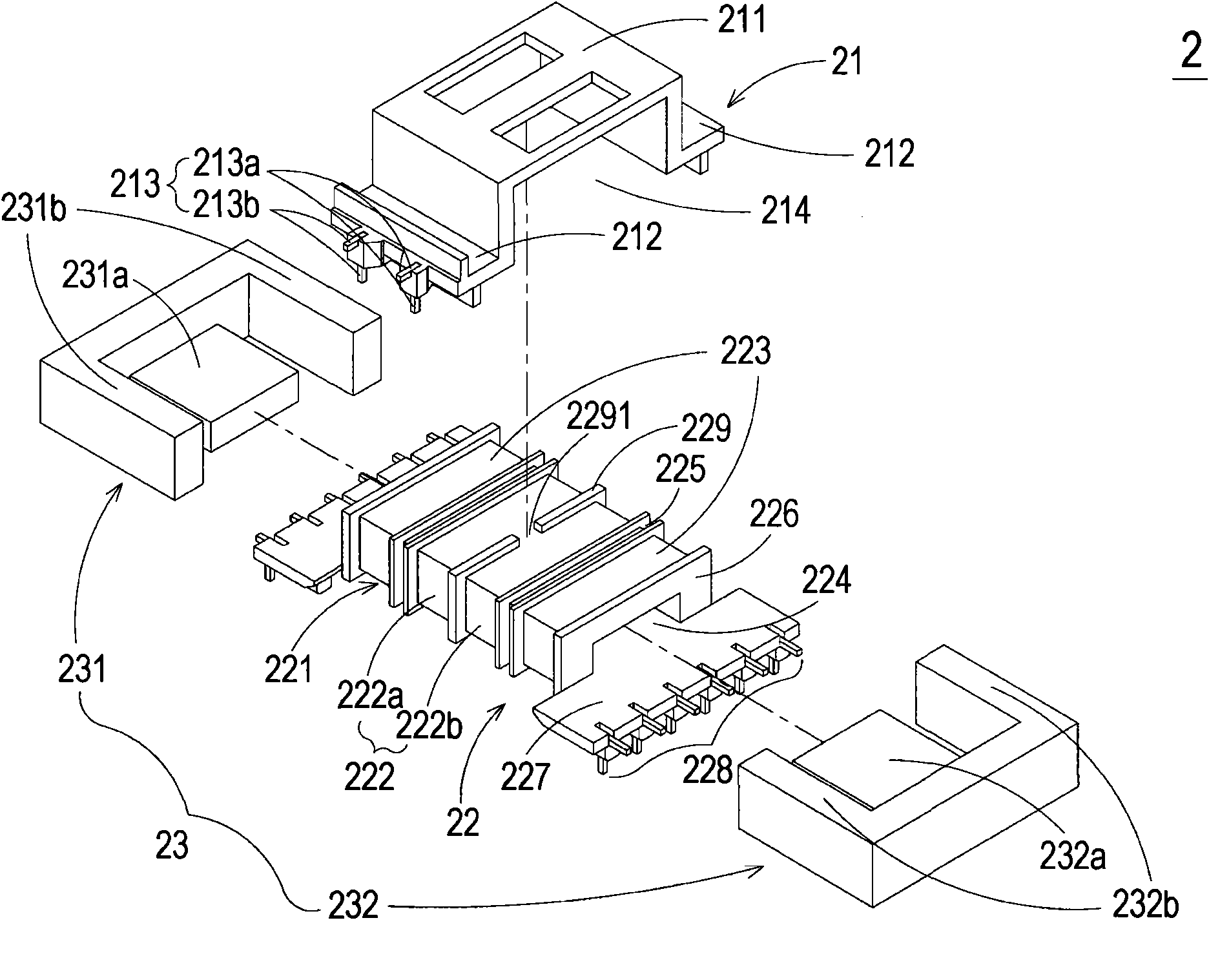
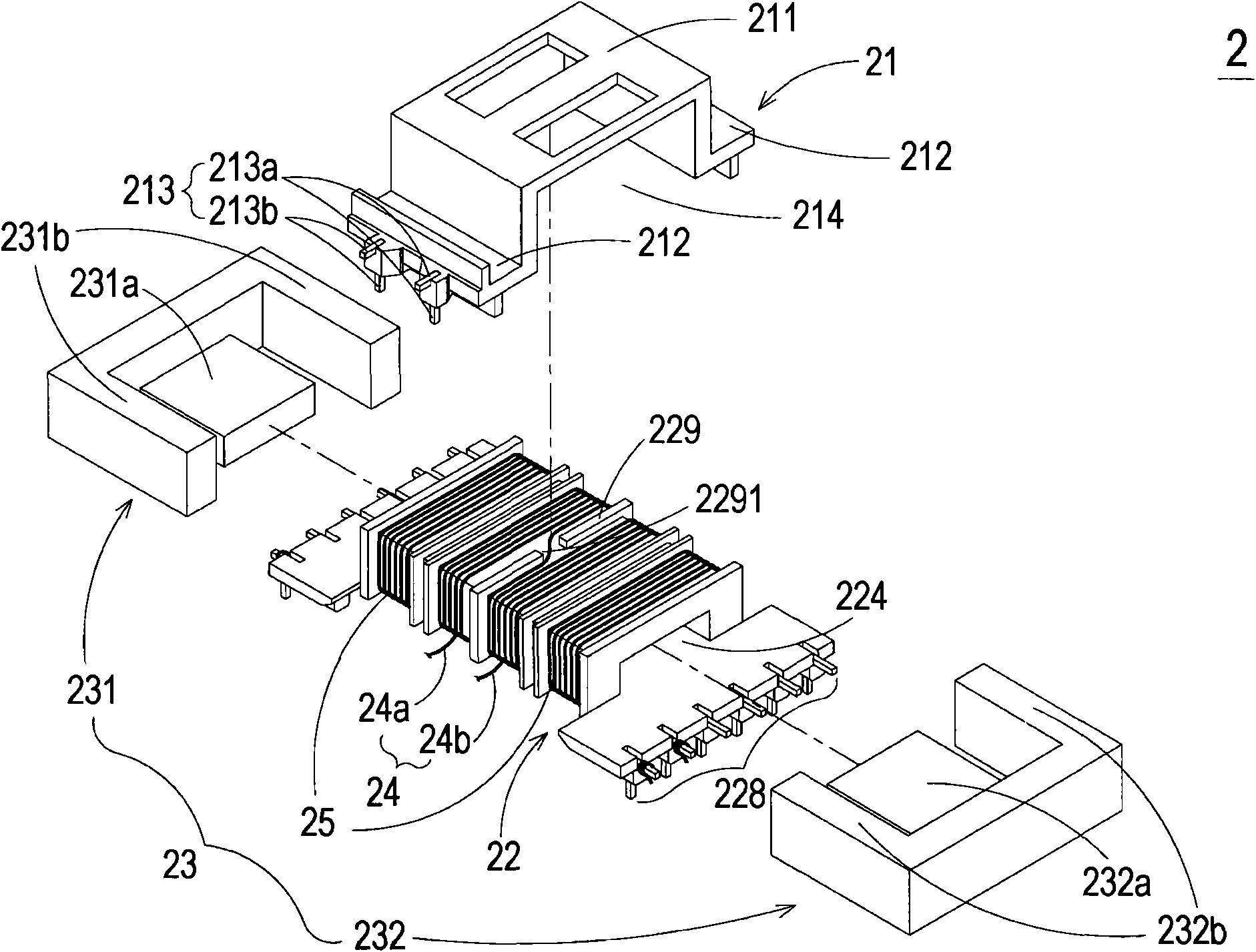
[0045] see Figure 2A , which is a schematic exploded structure diagram of the transformer structure in the first preferred embodiment of the present invention. As shown in the figure, the transformer 2 of the present invention mainly includes a cover body 21, a winding base 22, a magnetic core group 23, a primary winding 24 and a plurality of secondary windings 25 (such as Figure 2Bshown). Wherein, the cover body 21 is assembled with the winding base 22 and has a main body 211, an accommodating portion 212 and a plurality of guide pins...


PUM


Abstract

The present invention relates to a transformer structure comprising a cover, a bobbin, a channel, a primary winding coil, a plurality of secondary winding coils and a magnetic core assembly, wherein the cover is provided with a plurality of conductive connecting pins; the bobbin connected with the cover includes a body, a first winding coil area and a plurality of single groove second winding coil areas, and the plurality of single groove second winding coil areas are arranged in the two sides of the first winding coil area; the channel is penetrated through the body; the primary winding coilis winded around the first winding coil area of the bobbin, and is connected with the plurality of conductive connecting pins of the cover; the plurality of secondary winding coils are respectively winded around the plurality of single groove second winding coil areas of the bobbin; and part of the magnetic core assembly is arranged in the channel of the bobbin. By means of arranging a plurality of single groove second winding coil areas on the bobbin, the transformer structure can improve the current switching power and increase the winding coil space of the first winding coil area, and can reduce the heat energy generated during the operation of the transformer.

Description

technical field [0001] The invention relates to a transformer structure, in particular to a transformer structure with multiple single-slot second winding areas. Background technique [0002] Transformer is a magnetic component often used in various electrical equipment. It uses the principle of electric energy and magnetic energy conversion induction to adjust different voltages to make it reach the applicable range of electrical equipment. [0003] Generally speaking, the control of transformer leakage inductance (leaking inductance) is very important to the power converter, because it affects the power conversion efficiency of the power converter. In power supply systems of new generation electronic products such as liquid crystal displays (Liquid Crystal Display, LCD), transformers with leakage inductance are the mainstream, such as resonant transformers (LLC transformers). In this type of application , the current of the power supply system will first pass through the ...

Claims


Application Information

Patent Timeline
Patent Type & Authority Applications(China)
IPC IPC(8): H01F30/06H01F27/02H01F27/30H01F27/24
Inventor 曾祥益蔡辛卫
Owner DELTA ELECTRONICS INC
Why Eureka
Try Eureka