Low-input voltage bridgeless staggered voltage-multiplying power factor correction device

A power factor correction and low-voltage input technology, which is applied in the field of bridgeless interleaved voltage doubling power factor correction devices, can solve problems such as circuit conversion efficiency limitations

Inactive Publication Date: 2011-05-25
FUZHOU UNIV
View PDF0 Cites 5 Cited by
  • Summary
  • Abstract
  • Description
  • Claims
  • Application Information

AI Technical Summary

Problems solved by technology

However, since the circuit uses a rectifier bridge, the conversion efficiency of the circuit is limited

Method used


Image

  • Low-input voltage bridgeless staggered voltage-multiplying power factor correction device
  • Low-input voltage bridgeless staggered voltage-multiplying power factor correction device
  • Low-input voltage bridgeless staggered voltage-multiplying power factor correction device

Examples


Embodiment Construction

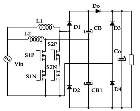
[0013] Such as figure 1 As shown, a low-voltage input bridgeless interleaved voltage doubling power factor correction device proposed by the present invention includes an AC input power supply Vin, power MOSFETs S1P, S1N, S2P, S2N, diodes D1, D2, D3, D4, Do, storage Capacitors CB1, CB, CO, inductors L1, L2.

[0014] figure 1 The power MOSFETs S1P, S1N, diodes D3, D4, DO, energy storage capacitors CB, CB1, and inductor L2 form a bridgeless interleaved BOOST circuit 1; power MOSFETs S2P, S2N, diodes D1, D2, D3, D4, DO and inductor L1 form a bridgeless interleaved BOOST circuit 2 . The power MOSFET S1P, the power MOSFET S1N, the power MOSFET S2P and the power MOSFET S2N work at high frequency, and the control driving signals work alternately.

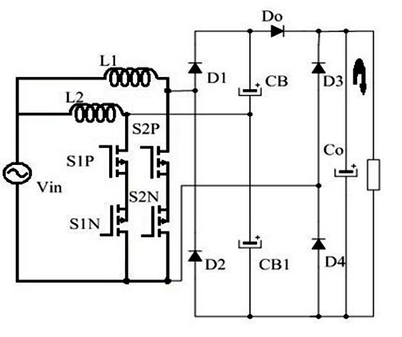
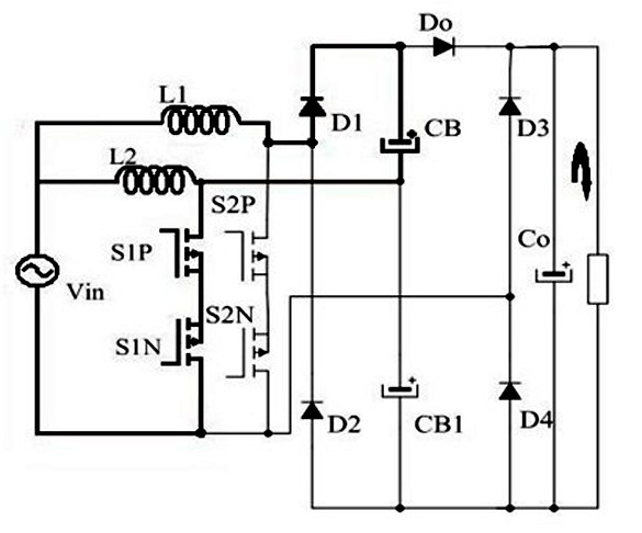
[0015] The four working modes of the low-voltage input bridgeless interleaved voltage doubling power factor correction device proposed by the present invention are as attached figure 2 , with image 3 , with Figure 4 , with Figur...


PUM


Abstract

The invention relates to a low-input voltage bridgeless staggered voltage-multiplying power factor correction device. A bridgeless staggered voltage-multiplying power factor correction (PFC) circuit consists of four power metal oxide semiconductor field effect transistors (MOSFET), two inductors and five diodes, and aiming at low-input voltage and high-power application occasions, the circuit conversion efficiency can be improved, and the circuit corrugation can be reduced further. The device integrates a diode rectifier bridge with the PFC circuit, has inherent voltage-multiplying function and can reduce an effective value of current. Therefore, the conduction loss can be reduced, the circuit corrugation is reduced, the efficiency is improved, and the device is suitable for the low-voltage and high-power application occasions.

Description

technical field [0001] The invention relates to a low-voltage input bridgeless interleaved voltage doubling power factor correction device, which has an inherent voltage doubling function, can reduce the effective value of the current, thereby reducing the conduction loss, and the interleaved structure can reduce circuit input and output ripples and improve efficiency. Background technique [0002] Due to the mandatory requirements of electromagnetic compatibility standards on the harmonics of the input current of the rectifier grid side, power factor correction technology has become a necessary and important technical means in recent years. In many power electronic devices, a typical power correction circuit uses a step-up BOOST converter connected in series between a diode rectifier bridge and a DC energy storage capacitor to achieve the above purpose. By controlling the on-off moment of the switch of the BOOST converter, the device can realize a power factor close to 1. ...

Claims


Application Information

Patent Timeline
Patent Type & Authority Applications(China)
IPC IPC(8): H02M1/42
CPCY02B70/126Y02B70/10Y02P80/10
Inventor 林维明
Owner FUZHOU UNIV
Why Eureka
Try Eureka