Rapid thermal processing chamber with shower head

A rapid heat treatment and chamber technology, applied in the field of heat treatment, can solve problems such as non-uniform endothermic or exothermic reactions

Active Publication Date: 2011-05-25
APPLIED MATERIALS INC
View PDF2 Cites 13 Cited by
  • Summary
  • Abstract
  • Description
  • Claims
  • Application Information

AI Technical Summary

Problems solved by technology

In addition, localized gas cooling or heating effects associated with the processing chamber design, as well as non-uniform endotherm

Method used


Image

  • Rapid thermal processing chamber with shower head
  • Rapid thermal processing chamber with shower head
  • Rapid thermal processing chamber with shower head

Examples


Embodiment Construction

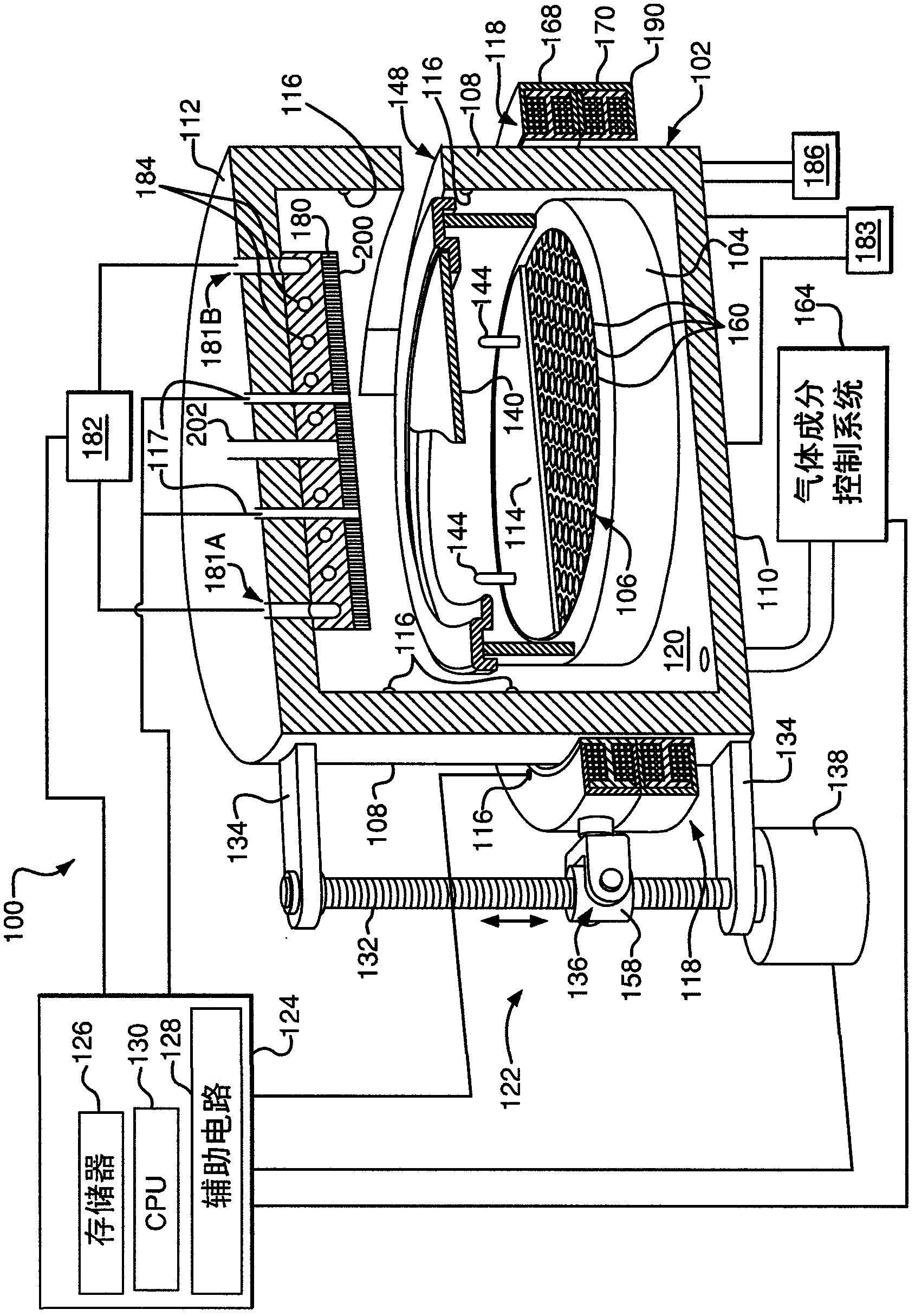
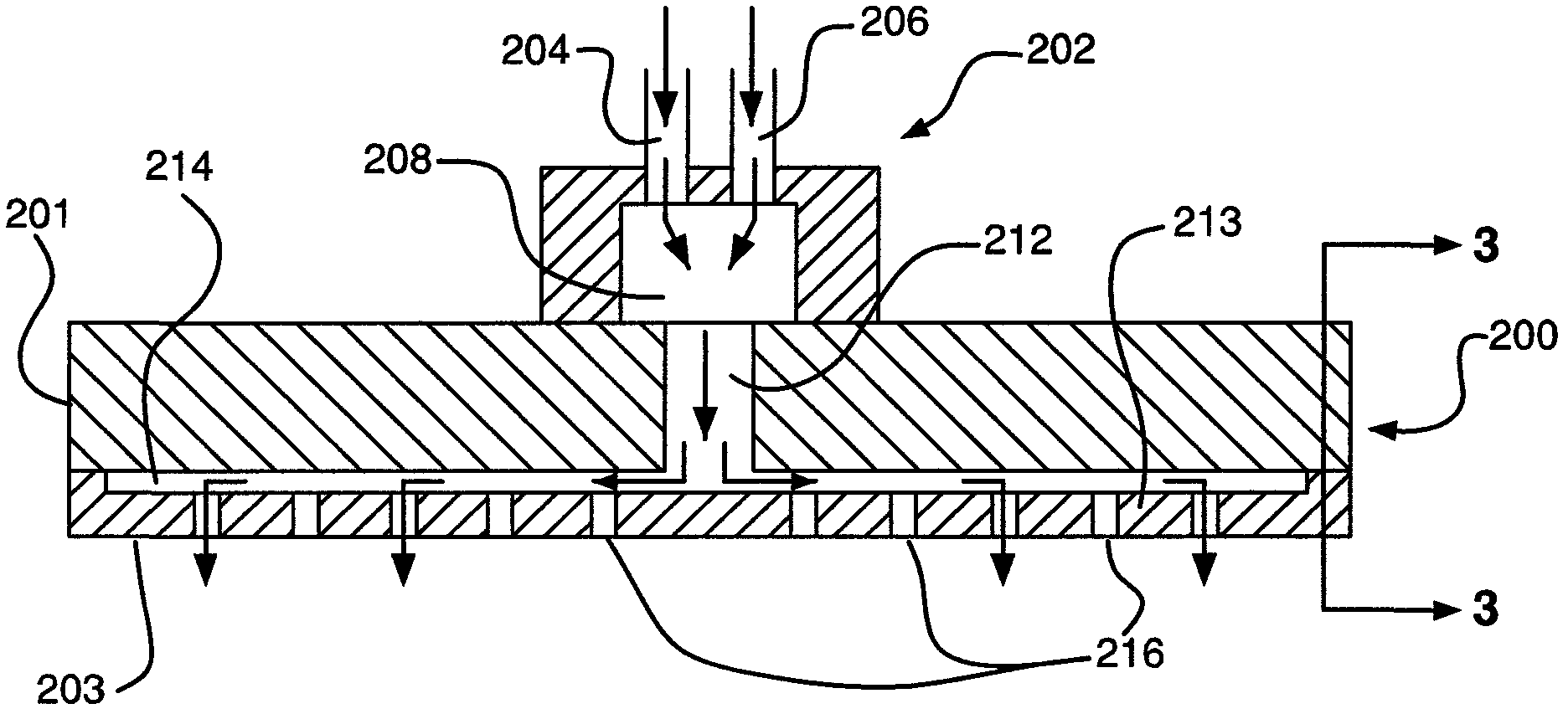
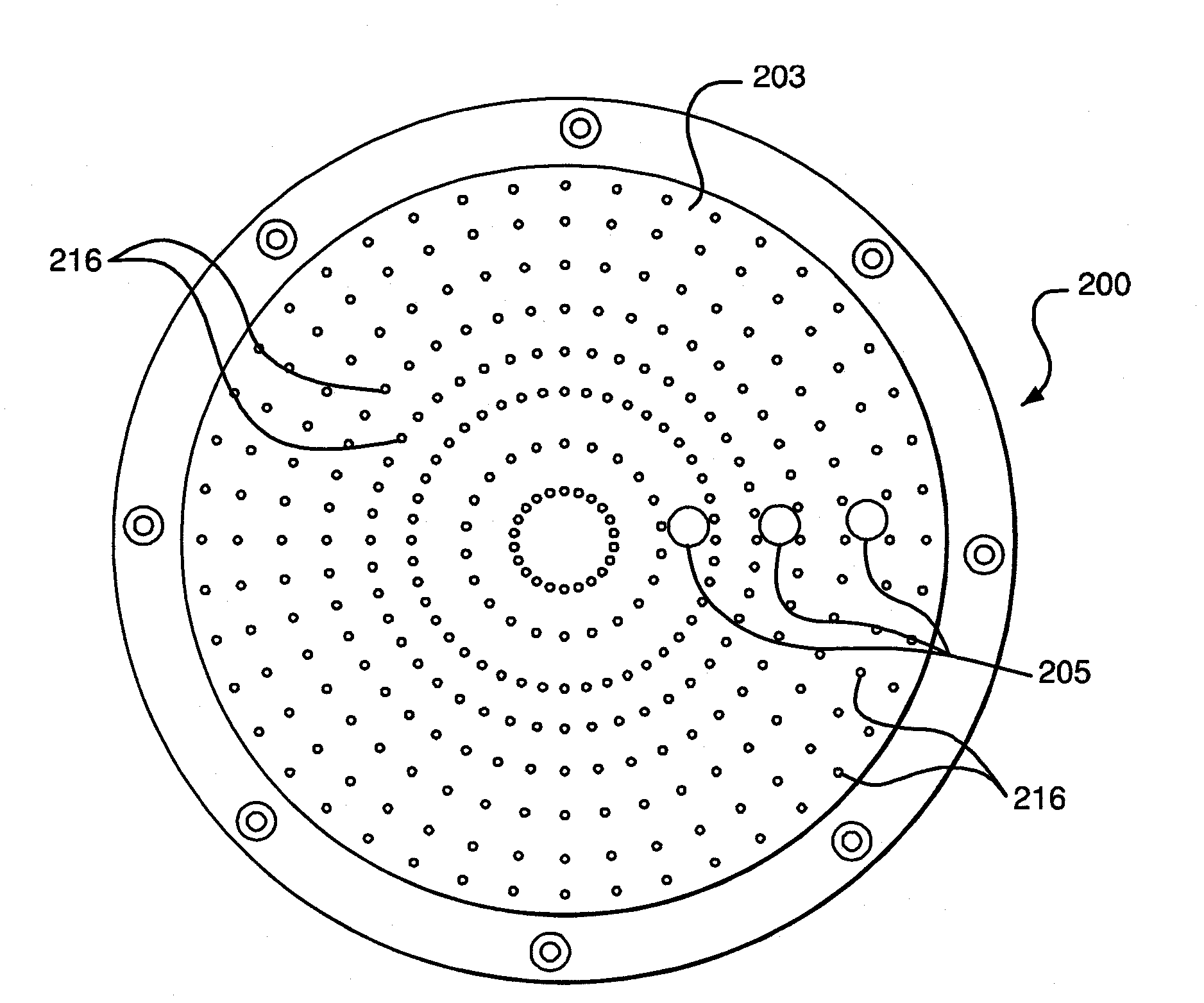
[0019] The embodiments described below generally relate to RTP systems that include a plate incorporating gas distribution outlets to distribute the gas evenly over the substrate, allowing rapid and controlled heating and cooling of the substrate. The panels can be absorptive, reflective, or a combination of both. As used herein, rapid thermal processing or RTP refers to an apparatus or process capable of uniformly heating a wafer at a rate of about 50°C / sec and higher, eg, 100-150°C / sec and 200-400°C / sec. Typical ramp-down (cooling) rates in an RTP chamber are between 80-150°C / sec. Some processes performed in RTP chambers require temperature variations across the substrate of less than a few degrees Celsius. Therefore, the RTP chamber must include a lamp or other suitable heating system and heating control system capable of heating at rates as high as 100-150°C / sec and 200-400°C / sec, unlike rapid thermal processing chambers that do not have the capability to A distinction i...


PUM


Abstract

Apparatuses and methods for thermally processing a substrate are provided. A chamber containing a levitating support assembly configured to position the substrate at different distances from a plate during the heating and cooling of a substrate. In one embodiment a plurality of openings on the surface of the plate are configured to evenly distribute gas across a radial surface of the substrate. The distribution of gas may couple radiant energy not reflected back to the substrate during thermal processing with an absorptive region of the plate to begin the cooling of the substrate. The method and apparatus provided within allows for a controllable and effective means for thermally processing a substrate rapidly.

Description

technical field [0001] Embodiments of the invention generally relate to thermal processing of semiconductor wafers and other substrates. More particularly, embodiments of the invention relate to rapid thermal processing of wafers from a radiation source, such as an array of incandescent lamps. Background technique [0002] The fabrication of integrated circuits from silicon or other wafers involves the steps of depositing multiple layers, photolithographically patterning the layers, and etching the patterned layers. Ion implantation is used to dope the active region of semiconductor silicon. The fabrication process also includes thermal annealing of the wafer for a variety of purposes including: de-implantation damage, and activation of dopants, crystallization, thermal oxidation and nitridation, silicidation, chemical vapor deposition, vapor phase doping, Thermal cleaning and other reasons. While the early days of silicon technology typically included heating multiple wa...

Claims


Application Information

Patent Timeline
IPC IPC(8): H01L21/324
CPCC23C16/45512H01L21/67207H01L21/67098C23C16/45565H01L21/67167F27B17/0025C23C16/4557C23C16/4404H01L21/67115C23C16/4584C23C16/481C23C16/45572H01L21/67109H01L21/324
Inventor 库赫斯特·索瑞伯基约瑟夫·M·拉内什沃尔夫冈·阿德霍尔德阿伦·M·亨特亚历山大·N·勒纳
Owner APPLIED MATERIALS INC
Why Eureka
Try Eureka