Tuning method for optic tunable filter
An optical filter and optical technology, applied in the field of optics and lasers, which can solve the problems of difficult control of coating surface shape accuracy and narrow bandwidth.
- Summary
- Abstract
- Description
- Claims
- Application Information
AI Technical Summary
Problems solved by technology
Method used
Image
Examples
Embodiment 1
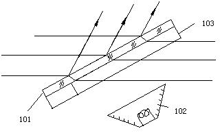
[0022] Embodiment 1: The refractive index or thickness of the optical plate is changed by changing the temperature field of the optical plate, thereby changing the optical path difference of the light in the optical plate, and realizing the tuning of the filter.
[0023] Due to the thermo-optic effect of the material, when the temperature field of the material is changed, the refractive index of the material will change, and the thickness of the material will also change with the temperature due to the effect of cold shrinkage and thermal expansion. Therefore, changing the temperature can change the amount of light in the plate The optical path difference within the etalon is realized, that is, the change of the effective cavity length of the etalon is realized, so as to realize the tuning of the filter. One of the ways to change the temperature is image 3 As shown, outside the ultra-thin optical parallel plate 101, a thermal energy radiation device 102 capable of radiating t...
Embodiment 2
[0024] Embodiment 2: The refractive index or thickness of the optical plate is changed by changing the electric field of the optical plate, thereby changing the optical path difference of the light in the optical plate, and realizing the tuning of the filter.
[0025] Due to the electrostrictive effect or inverse piezoelectric effect of the material, the thickness of the plate will change when the electric field of the material is changed, and the refractive index of the material will also change due to the electro-optic effect of the material, so the change of the electric field can play a role in tuning the etalon. effect. One of the ways to change the voltage is Figure 4 As shown in the figure, transparent conductive films 202 and 203 are respectively coated on the two optical surfaces of the ultra-thin optical parallel plate 201, and electrodes 204 are added on the conductive films, and the electric field of the optical plate can be changed by changing the electrode volta...
Embodiment 3
[0026] Embodiment 3: The optical filter is tuned by changing the refractive index of the optical plate by changing the magnetic field of the optical plate.
[0027] Some materials have magneto-optical effect, and their refractive index will change with the magnetic field. Therefore, these materials are made into an ultra-thin optical parallel plate 301, and by changing the magnetic field of the optical plate, the etalon can also be tuned. One of the ways to change the magnetic field is Figure 5 As shown, two inductors 302 and 303 are added to the two sides of the ultra-thin optically parallel flat plate 301 in directions perpendicular to the flat plate. By changing the currents of the two inductors, the magnetic field in the plate can be changed, and finally the filter can be tuned.
PUM
 Abstract
Description
Claims
Application Information
 - R&D
- Intellectual Property
- Life Sciences
- Materials
- Tech Scout
- Unparalleled Data Quality
- Higher Quality Content
- 60% Fewer Hallucinations
Browse by: Latest US Patents, China's latest patents, Technical Efficacy Thesaurus, Application Domain, Technology Topic, Popular Technical Reports.
© 2025 PatSnap. All rights reserved.Legal|Privacy policy|Modern Slavery Act Transparency Statement|Sitemap|About US| Contact US: help@patsnap.com


