
Bearingless synchronous reluctance motor torque and suspension force direct controller and construction method thereof

A technology of synchronous reluctance motor and torque controller, which is applied in the direction of motor generator control, AC motor control, electronic commutation motor control, etc., and can solve the problem of restricting the suspension force control accuracy and dynamic response performance, and the control effect is difficult to achieve theoretical The results of the analysis, the problem of low capacity utilization, etc., achieve the effect of overcoming the limitation of suspension force control accuracy and dynamic response performance, excellent motor operation performance, and excellent dynamic and static performance

Inactive Publication Date: 2011-06-01
JIANGSU UNIV
View PDF2 Cites 24 Cited by
  • Summary
  • Abstract
  • Description
  • Claims
  • Application Information

AI Technical Summary

Problems solved by technology

[0003] At present, the decoupling control of bearingless synchronous reluctance motor torque and suspension force mainly adopts the current tracking inverter with high switching frequency and low capacity utilization rate, and adopts vector control. The system relies too much on complex motor parameters and vector Coordinate transformation, the control of the suspension force is in an open-loop state, which limits the accuracy and dynamic response performance of the suspension force control, making it difficult for the actual control effect to reach the theoretical analysis results

Method used


Image

  • Bearingless synchronous reluctance motor torque and suspension force direct controller and construction method thereof
  • Bearingless synchronous reluctance motor torque and suspension force direct controller and construction method thereof
  • Bearingless synchronous reluctance motor torque and suspension force direct controller and construction method thereof

Examples


Embodiment Construction

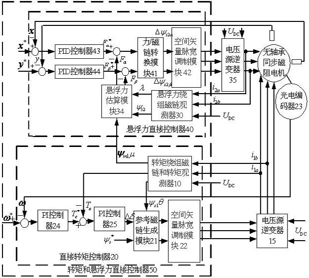
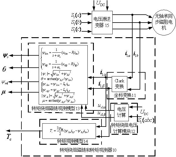
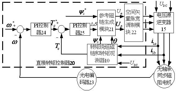
[0020] Such as figure 1 In the present invention, the bearingless synchronous reluctance motor torque and suspension force direct controller 50 is composed of a direct torque controller 20 and a suspension force direct controller 40 . Wherein, direct torque controller 20 is made up of two PI controllers 24,25, torque winding flux linkage and torque observer 10, reference flux linkage generating module 21 and space vector pulse width modulation module 22; two PI controllers 24, 25, the reference flux linkage generation module 21 and the space vector pulse width modulation module 22 are sequentially connected in series, the space vector pulse width modulation module 22 is connected to the external voltage source inverter 15, and the voltage source inverter 15 is connected to the bearingless Synchronous reluctance motor. The torque winding flux linkage and the input of the torque observer 10 are connected to the bearingless synchronous reluctance motor, and the output is respec...


PUM


Abstract

The method discloses a bearingless synchronous reluctance motor torque and suspension force direct controller and a construction method thereof. The bearingless synchronous reluctance motor torque and suspension force direct controller consists of a direct torque controller with a rotating speed and torque double closed loop and a suspension force direct controller with a rotor displacement and suspension force double closed loop, wherein the direct torque controller consists of two proportional plus integral (PI) controllers, a torque winding flux linkage and a torque observer, a reference flux linkage generating module and a space vector pulse width modulation module; and the suspension force direct controller consists of two proportional plus integral plus derivative (PID) controllers, a torque winding flux linkage and torque observer, a suspension force winding flux linkage observer, a suspension force estimation module, a force / flux linkage conversion module and a space vector pulse width modulation module. By the controller and the construction method, motor torque and radial suspension force are independently controlled, stable suspension and operation of a motor rotor are ensured and high motor operating performance is achieved.

Description

technical field [0001] The invention relates to a bearingless synchronous reluctance motor used in high-speed ultra-high-speed numerical control machine tools, turbomolecular pumps, centrifuges, compressors, electromechanical energy storage, aerospace and other special electric transmission fields, especially relates to a bearingless synchronous reluctance motor rotor. Torque and levitation force direct controller and construction method for high performance control of bearingless synchronous reluctance motor. Background technique [0002] Bearingless synchronous reluctance motor is a multivariable, nonlinear and strongly coupled controlled object, and its radial position and speed are difficult to be accurately controlled by external signals. To achieve stable suspension and operation of the motor rotor, decoupling control of the motor torque and suspension force must be performed. [0003] At present, the decoupling control of bearingless synchronous reluctance motor torq...

Claims


Application Information

Patent Timeline
Patent Type & Authority Applications(China)
IPC IPC(8): H02P21/14H02P25/08H02P27/08H02N15/00
Inventor 胡维超陆静朱睿智吴熙张婷婷朱熀秋
Owner JIANGSU UNIV
Learn More