Waste heat recovery system

A technology for waste heat recovery and exhaust gas, which is applied to machines using waste heat, lighting and heating equipment, and combustion methods.

Inactive Publication Date: 2011-06-08
前田和彦
View PDF7 Cites 6 Cited by
  • Summary
  • Abstract
  • Description
  • Claims
  • Application Information

AI Technical Summary

Problems solved by technology

Since VOC contributes to global warming, it is regulated by the Air Pollution Control Act, and its stench affects nearby residents

Method used


Image

  • Waste heat recovery system
  • Waste heat recovery system
  • Waste heat recovery system

Examples


Embodiment 1

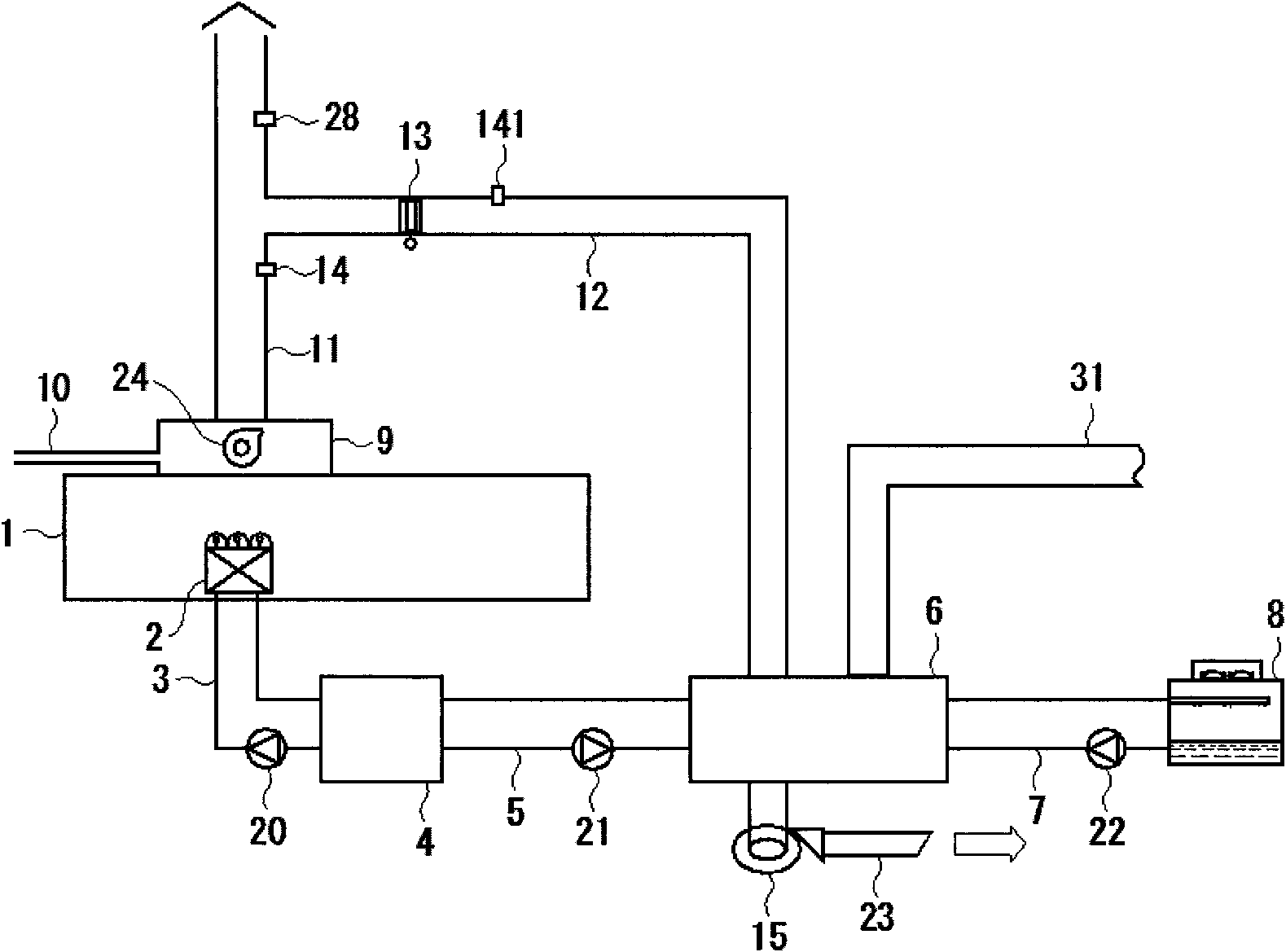
[0035] The waste heat recovery system of Embodiment 1 is as figure 1shown. In this specific embodiment, the device that generates VOC is an offset printing machine. The offset printing machine 1 is provided with a cooler 2 for cooling rolls. A cold water buffer tank 4 is connected to the cooler 2 through a circulation pipe 3 . The cold water buffer tank 4 is connected with an exhaust gas absorption refrigerator 6 through a circulation pipe 5 . The waste gas absorption refrigerator 6 is connected to a cooling tower 8 through a circulation pipe 7 . In addition, 20, 21, 22 in the figure are circulation pumps.

[0036] The offset printing machine 1 is provided with a drying function to dry the ink of the printed matter. The offset printing machine 1 is provided with a combustion-type deodorizing device 9 as a VOC treatment device for deodorizing VOC gas containing odor generated by drying ink through the drying function. The fuel is introduced into the deodorizing device 9 t...

Embodiment 2

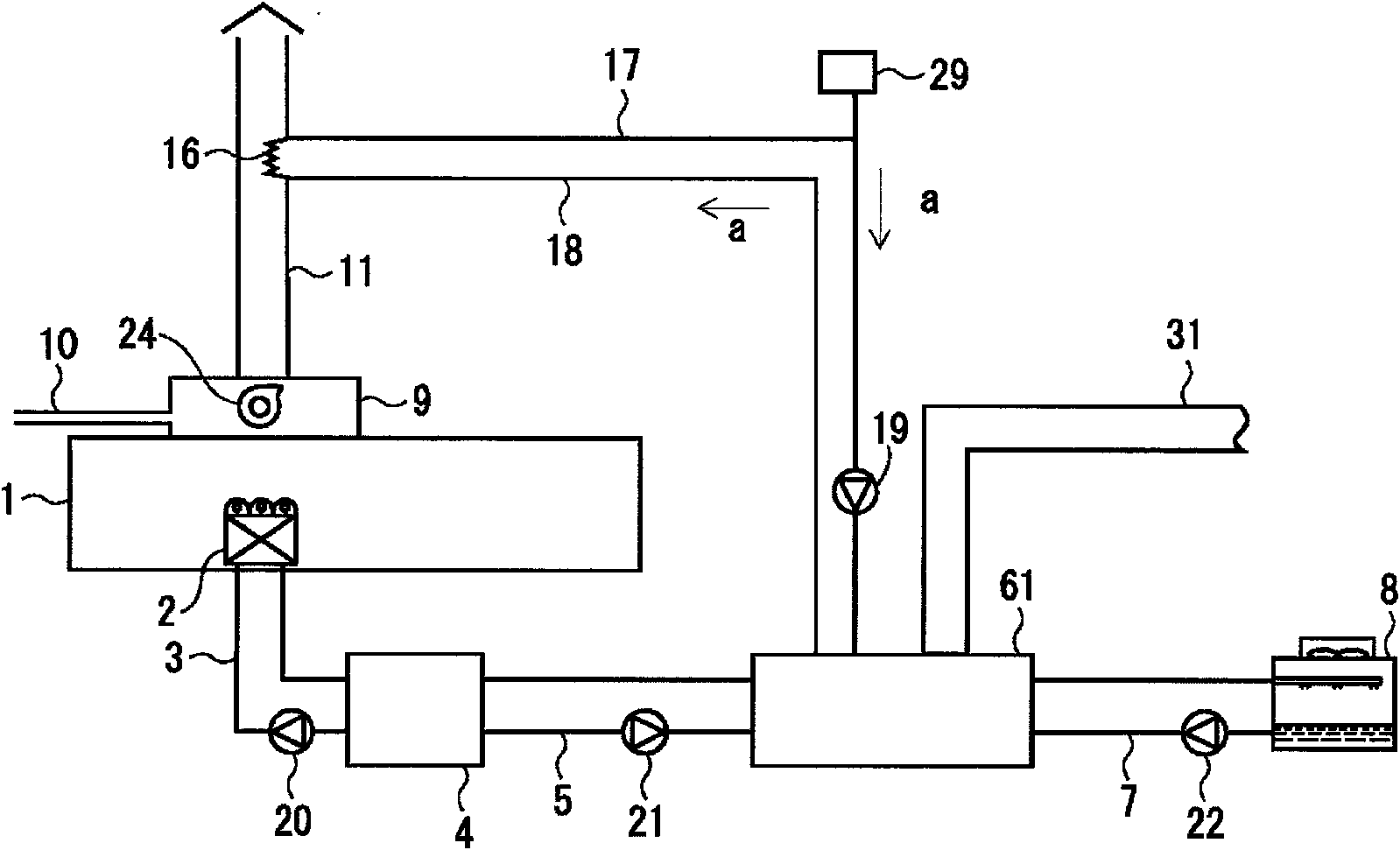
[0052] The waste heat recovery system of the second specific embodiment shown in the figure is as figure 2 shown. In the same configuration as the waste heat recovery system of the first embodiment, the same reference numerals are used, and descriptions thereof are omitted.

[0053] The difference between the second embodiment and the first embodiment is that a second heat exchanger 16 is provided in the middle of the chimney 11 , and high-temperature water circulation pipes 17 and 18 are connected to the second heat exchanger 16 . The high-temperature water circulation pipes 17 and 18 are connected to an absorption refrigerator 61 . A circulation pump 19 is provided in the middle of the high-temperature water circulation pipe 17 , and high-temperature water circulates between the absorption refrigerator 61 and the second heat exchanger 16 . The high temperature water circulation pipe 17 is provided with an expansion tank 29 to absorb the increase in the volume of the high ...

Embodiment 3

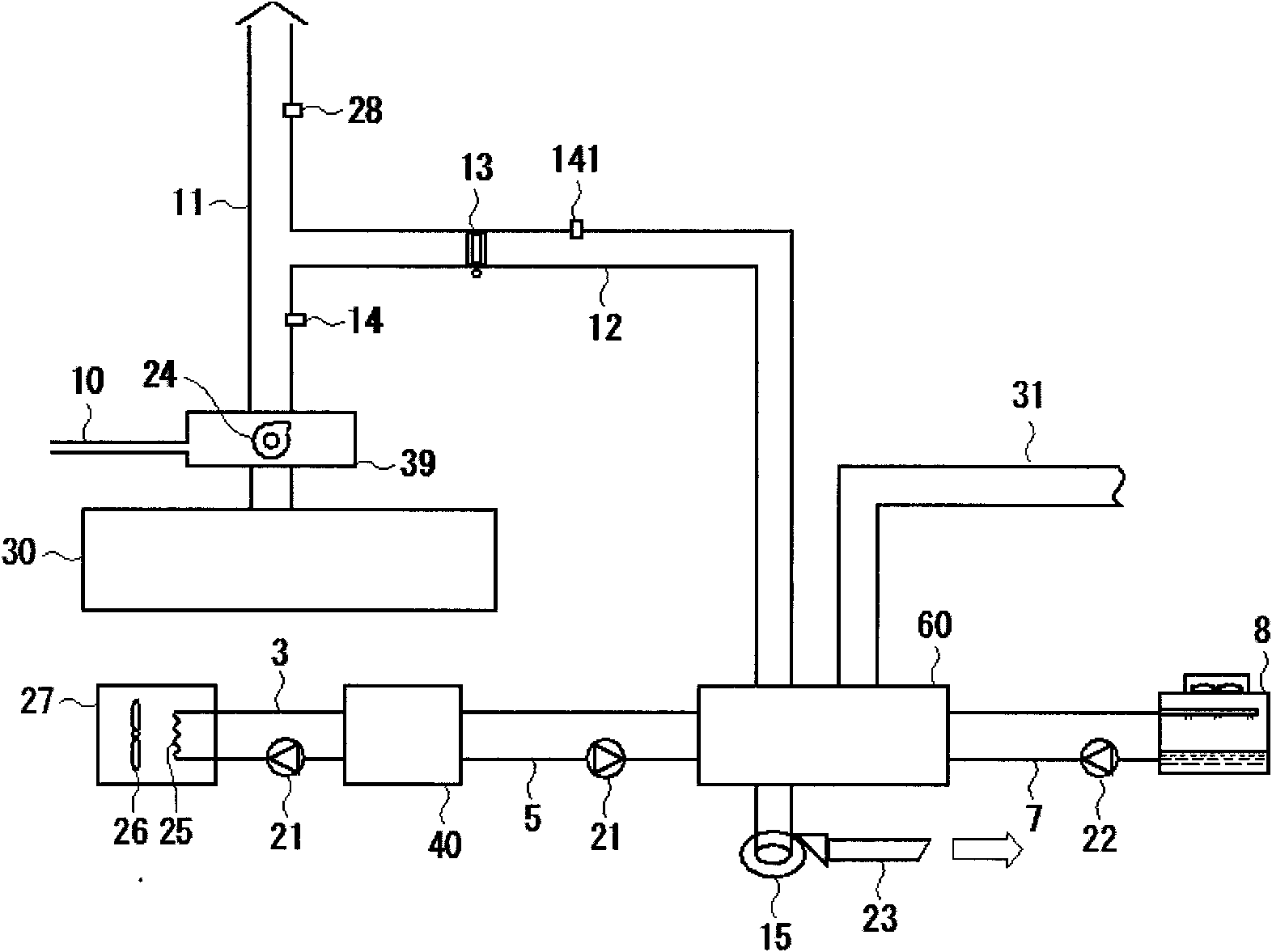
[0061] The waste heat recovery system of embodiment three such as image 3 shown. The same reference numerals are used for the same components as those in the waste heat recovery systems of the first and second embodiments, and the description thereof will be omitted. In this specific embodiment, the equipment that generates VOC is the gravure printing machine 30 . The VOC-containing gas generated by the ink drying function of drying the printed matter of the gravure printing machine 30 is combusted and pyrolyzed by the combustion-type or regenerative combustion-type VOC treatment device 39 . The exhaust gas discharged from the VOC treatment device 39 passes through the chimney 11 and is discharged to the outside air.

[0062] The chimney 11 is connected with one end of an air duct 12 as an exhaust gas duct in the middle. The other end of the air pipe 12 is connected to an exhaust gas absorption type cold and hot water generator 60 . The exhaust gas absorption type cold an...


PUM


Abstract

The present invention relates to a waste heat recovery system which utilizes waste heat discharged from a volatile organic compound (VOC) treatment apparatus to realize green and energy saving proposes. An exhaust gas type absorption chiller heater produces cold water or hot water utilizing heat energy of exhaust gas discharged from a VOC treatment apparatus which executes combustion and component decomposition at a high temperature of VOC emitted from a VOC emitting apparatus in operation. Using the cold water or hot water to an air-conditioning apparatus of a factory or a cooler of the VOC emitting apparatus achieves environmental friendliness and energy conservation measures. Since clean exhaust gas discharged from the VOC treatment apparatus is guided into the exhaust gas type absorption chiller heater, durability of the exhaust gas type absorption chiller heater can be maintained.

Description

Technical field [0001] The invention relates to a waste heat recovery system. More specifically, it involves a combustion-type VOC treatment device that processes volatile organic solvents (hereinafter referred to as "VOC") generated by gravure printing machines or equipment related to semiconductor production, and an air-conditioning equipment system that utilizes waste heat emitted by a combustion-type VOC treatment device. As well as air conditioning equipment systems and printing press cooling systems that utilize waste heat emitted by combustion deodorization devices such as offset printing machines. Background technique [0002] Gravure printing machines, equipment related to semiconductor production, offset printing machines, etc. will produce VOC gases. Since VOC contributes to global warming, it is regulated by the Air Pollution Prevention and Control Act, and its stench can affect nearby residents. Therefore, VOC-containing gases need to be decomposed by high tem...

Claims


Application Information

Patent Timeline
Patent Type & Authority Applications(China)
IPC IPC(8): F23G7/06F25B27/02
CPCF23G2206/201B01D53/343B41F13/22B01D2258/0216F23G5/46F23G7/065B01D2257/708Y02E20/30Y02P70/10Y02P80/10
Inventor 前田和彦
Owner 前田和彦
Why Eureka
Try Eureka