Metal stud welding system combined with friction heat source
A welding system and stud technology, used in welding equipment, metal processing equipment, non-electric welding equipment, etc., can solve the problem that medium and large diameter studs cannot be directly welded, and avoid large upsetting force and friction studs. Insufficient welding calorific value to achieve the effect of effective solid-phase welding
- Summary
- Abstract
- Description
- Claims
- Application Information
AI Technical Summary
Problems solved by technology
Method used
Image
Examples
Embodiment 1
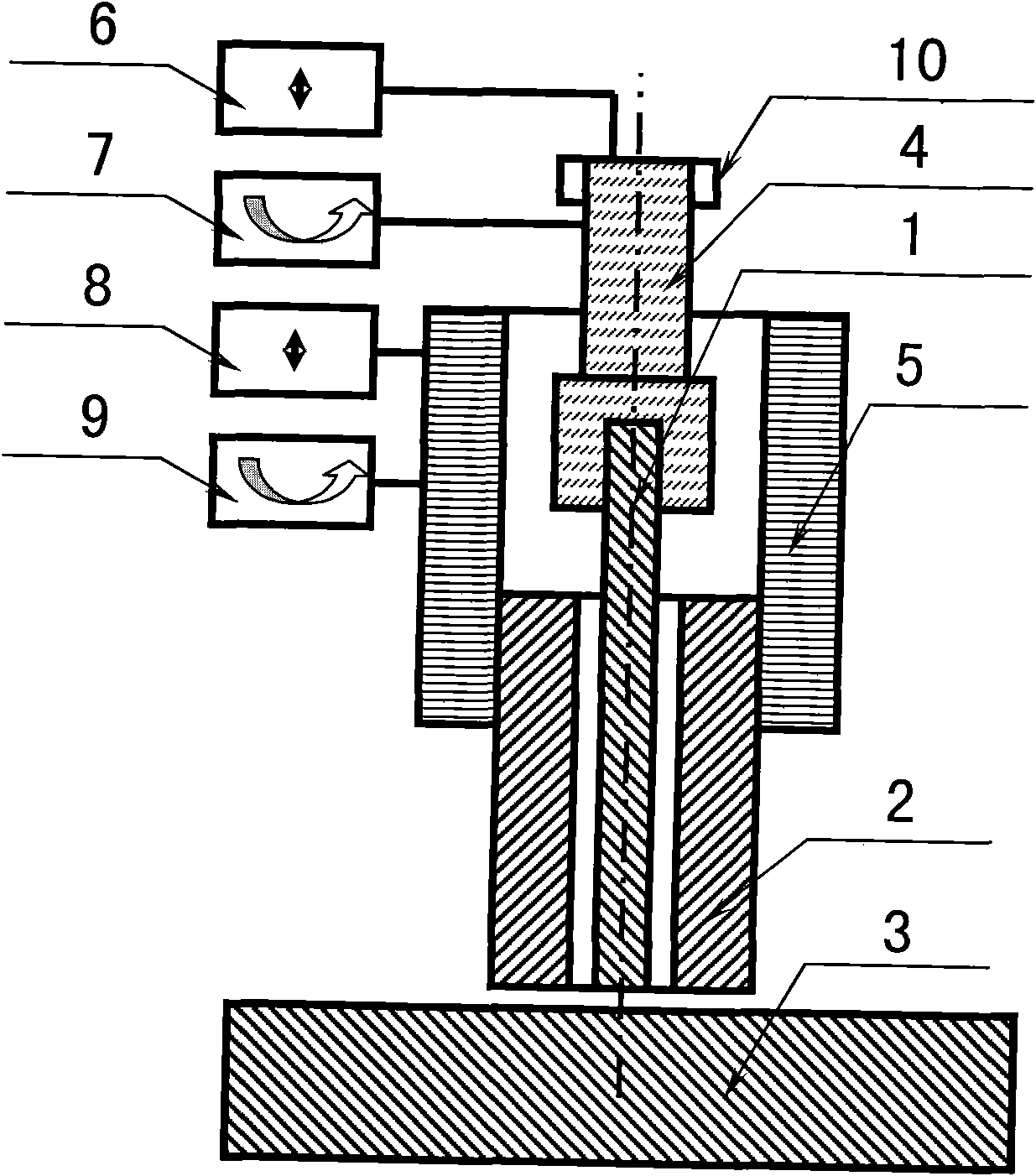
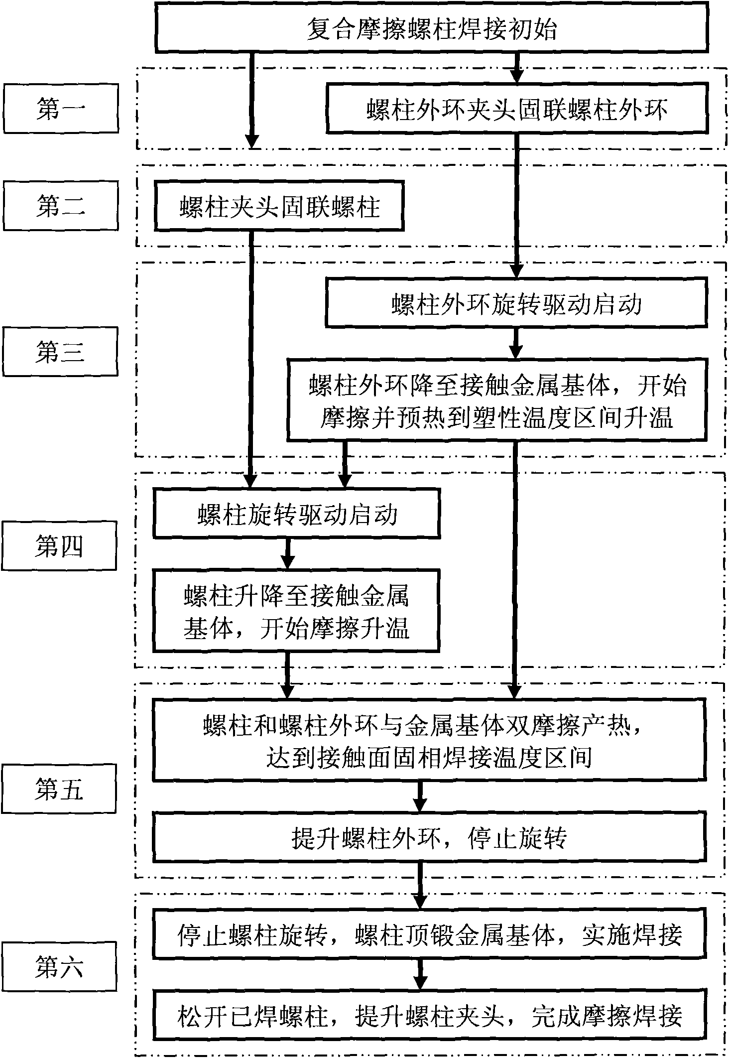
[0016] Example 1. combine figure 1 with figure 2 , a metal stud welding system with a composite friction heat source proposed by the present invention, mainly consists of a metal stud [1], a stud outer ring [2], a metal matrix [3], a stud chuck [4], a stud Outer ring chuck [5], stud axial displacement device [6], stud rotation device [7], stud outer ring axial displacement device [8], stud outer ring rotation device [9] and stud Brake [10] is formed. Wherein, metal stud [1] is the metal stud of shapes such as circular solid metal stud, circular hollow metal stud or square metal stud; Stud outer ring [2], stud chuck [4] and Stud outer ring collet [5] matches the type of metal stud [1] and metal base [3]; stud axial displacement device [6], stud rotation device [7], stud outer ring shaft The configuration requirements and working methods of the displacement device [8], the stud outer ring rotation device [9] and the stud brake [10] are basically the same as those of the exi...
Embodiment 2
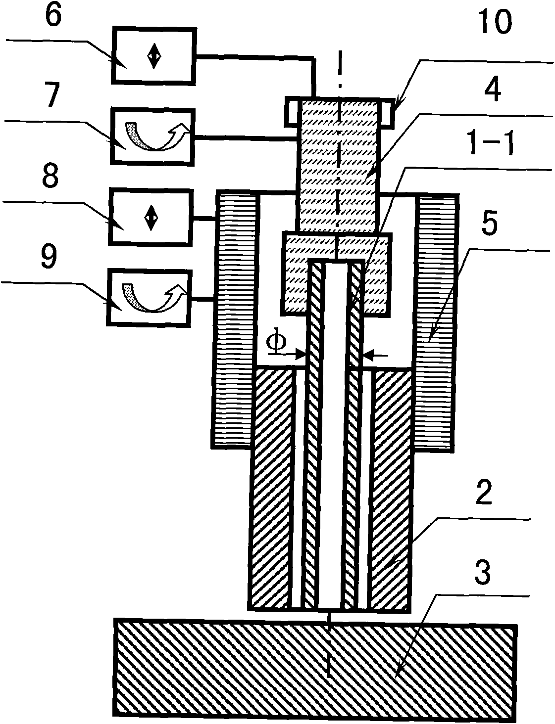
[0019] Example 2. combine image 3, the metal stud welding system for the composite friction heat source of the circular hollow stud proposed by the present invention mainly consists of a circular hollow metal stud [1-1], a stud outer ring [2], a metal matrix [3] , stud chuck [4], stud outer ring chuck [5], stud axial displacement device [6], stud rotation device [7], stud outer ring axial displacement device [8], screw Column outer ring rotating device [9] and stud brake [10] are formed. Among them, an aluminum circular hollow metal stud [1-1] with a diameter (φ) greater than or equal to 10 mm or a steel circular hollow metal stud [1-1] with a diameter greater than or equal to 25 mm. Utilize the auxiliary friction preheating between the outer ring [2] of the large-diameter stud and the metal matrix [3] to increase the temperature of the metal matrix [3] and increase the total heat input of welding. Through the friction between the stud outer ring [2] and the circular hollo...
Embodiment 3
[0020] Example 3. combine Figure 4 with Figure 5 , the metal stud welding system for the compound frictional heat source of the square metal stud proposed by the present invention mainly consists of the square metal stud [1-2], the stud outer ring [2], the metal matrix [3], the stud Chuck [4], stud outer ring chuck [5], stud axial displacement device [6], stud rotation device [7], stud outer ring axial displacement device [8], stud outer ring Swivel device [9] and stud brake [10] are formed. Among them, the square metal stud [1-2] is an aluminum square metal stud with a cross-sectional dimension (side length B) greater than or equal to 10×10 mm or a steel square metal stud with a cross-sectional dimension greater than or equal to 25×25 mm. Utilize the auxiliary friction preheating of the outer ring [2] of the large-diameter stud to increase the temperature of the metal substrate [3] and increase the total heat input of welding. Through the friction between the stud outer...
PUM
| Property | Measurement | Unit |
|---|---|---|
| diameter | aaaaa | aaaaa |
| diameter | aaaaa | aaaaa |
Abstract
Description
Claims
Application Information
 - R&D
- Intellectual Property
- Life Sciences
- Materials
- Tech Scout
- Unparalleled Data Quality
- Higher Quality Content
- 60% Fewer Hallucinations
Browse by: Latest US Patents, China's latest patents, Technical Efficacy Thesaurus, Application Domain, Technology Topic, Popular Technical Reports.
© 2025 PatSnap. All rights reserved.Legal|Privacy policy|Modern Slavery Act Transparency Statement|Sitemap|About US| Contact US: help@patsnap.com


