Numerical control machine tool wear monitoring method

A technology of tool wear and CNC machine tools, applied in the field of real-time monitoring and online tool wear status, which can solve problems affecting the normal processing of machine tools, changing the structure of machine tools, and unfixed values, so as to achieve real-time monitoring of tool wear status, improve the scope of application, The effect of easy installation

Inactive Publication Date: 2011-06-15
HUAZHONG UNIV OF SCI & TECH +1
10 Cites 76 Cited by

AI-Extracted Technical Summary

Problems solved by technology

The method based on volume loss characteristics requires downtime detection, which takes man-hours and makes it difficult to achieve online real-time monitoring
Acoustic emission, vibration and other methods are inconvenient for signal monitoring, troublesome sensor installation, affecting the normal processing of the machine tool, and even need to change the structure of the machine tool, so it can only be u...

Abstract

The invention belongs to the field of numerical control machine tool wear measurement, and discloses a numerical control machine tool wear monitoring method. In the method, servo drive motor current signals of a numerical control machine can reflect the change of a cutting load along with the tool wear; the acquired servo drive current signals are analyzed; the signals are decomposed in a frequency domain by a wavelet packet decomposition technology, and time-frequency domain characteristics of the signals in each frequency domain range are obtained and a plurality of characteristics stronglycorrelated to the tool wear are automatically selected; the tool wear process is learned through a neural network and a tool wear rule is obtained; in reverse, the tool wear characteristics are obtained in real time and are matched with the tool wear rule obtained through learning so as to monitor the tool wear state. The method solves a problem that the conventional tool wear monitoring method cannot realize online real-time monitoring, the servo drive signals of the numerical control machine are utilized, the integration with a numerical control system is easy to realize, the monitoring cost is reduced and the monitoring accuracy is ensured.

Application Domain

Technology Topic

Numerical control systemWavelet packet decomposition +7

Image

  • Numerical control machine tool wear monitoring method
  • Numerical control machine tool wear monitoring method
  • Numerical control machine tool wear monitoring method

Examples

  • Experimental program(1)

Example Embodiment

[0021] The present invention will be further explained below in conjunction with the drawings:
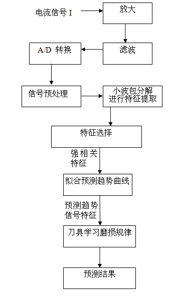
[0022] The tool wear state monitoring method of the present invention obtains the current signal of the machine tool drive motor, and goes through a series of signal processing and feature extraction and selection processes, and finally through the tool wear monitoring process, realizes the monitoring of the tool wear VB.
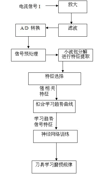
[0023] First, establish the tool learning wear law in the learning library through the following steps:
[0024] (1) Use the Hall current sensor to measure the three-phase output current of the drive motor of the CNC machine tool;
[0025] (2) Amplify, filter and A/D convert the measured output current to obtain the current digital signal, which is the processing signal;
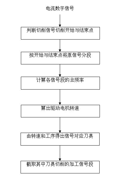
[0026] (3) Preprocessing the processing signal to obtain the current signal segment when learning the cutting tool;
[0027] The processing signals obtained through step (2) include machine start and stop, dry running, learning tool cutting and other tool cutting signals.
[0028] image 3 In the process, the processing signal is monitored by judging the start and end point of the cutting signal of each tool, and the processing signal is divided into various processing signals, and each processing signal corresponds to a tool. Analyze the motor speed corresponding to each segment of the processing signal, obtain the cutting tool corresponding to each segment of the processing signal, and obtain the learning tool processing signal segment. Finally, intercept the current signal segment when the tool is cutting in the learning tool processing signal.
[0029] Figure 4 In, the machining signals of the machine tool in two machining cycles are monitored. One machining cycle includes the machining signals of 6 tools. The processing signal of the learning tool needs to be extracted from the processing signal obtained from the initial monitoring. The acquired learning tool processing signals include a series of signals such as start, dry run, cutting processing, and stop. Figure 5 Shown.
[0030] Step (3) includes the following specific processes:
[0031] (3.1) Judge the start and end point of cutting of the processing signal;
[0032] The acquired initial processing signals include the processing signals of multiple tools, and the learning tool processing signals need to be selected from the initial processing signals. Since multiple tools are involved in the cutting process, the drive motor stops when the tool is changed, and the single-phase current variance value is small; when the tool starts to process, the drive motor rotates, and the single-phase current variance value is large. Calculate the variance of the single-phase current segment by segment and compare it with the set variance threshold. The threshold setting process is: first calculate the single-phase current variance value M when the drive motor stops rotating 1 , Then calculate the single-phase current variance value M when the drive motor is rotating 2 , Then the variance threshold value M = M 1 +1/3(M 2 -M 1 )=2/3M 1 +1/3M 2.When it is greater than the threshold, it is considered that the tool is about to start processing, which is the starting point of processing. Later, when the variance value is less than the threshold, the tool is considered to have completed the processing process. From this, the start and end points of the processing signal are determined.
[0033] (3.2) Divide the processing signal into each segment of processing signal.
[0034] (3.3) Calculate the main frequency of each processing signal;
[0035] (3.4) Convert the main frequency of each processing signal into the driving motor speed;
[0036] (3.5) According to the different speeds of different tools and the processing sequence of multiple tools, identify the processing signal segment corresponding to the learning tool;
[0037] (3.6) Cut the cutting signal segment from the processing signal segment of the learning tool.
[0038] (4) Use the wavelet packet decomposition method to process the cutting signal segment of the learned tool to obtain multiple signal characteristics;
[0039] (4.1) First, the learning tool processing signal segment obtained in step (3) is decomposed in multiple frequency segments by the wavelet packet decomposition method. A layer of wavelet packet decomposition can divide the original frequency band into two, and a k-layer wavelet packet can decompose the original frequency band into 2 k There are two frequency bands, which can subdivide the frequency bands and improve the resolution of the frequency domain. The k value is usually obtained by the following formula:
[0040] k = lgf - lg 50 lg 2 Where f is the sampling frequency of the signal
[0041] (4.2) Calculate and learn the mean value, variance and total energy of the cutting signal section of the tool in each frequency section respectively, and obtain multiple signal characteristics.
[0042] (5) Choose 4 signal features that are strongly related to tool wear as learning signal features;
[0043] Analyze the correlation between tool wear and each signal feature, and select four of the signal features that are strongly related to tool wear as the predicted signal feature for learning tool wear status. The correlation analysis process is as follows: First, make the sliding average curve of each signal feature with the processing time, and obtain the sliding average curve S of the tool in the two life cycles. 1 (x), S 2 (x); then calculate The smaller the e, the stronger the correlation between the signal feature and the tool wear, and the four signal features with the strongest correlation are selected as the learning signal feature. x i Represents the tool processing time, N represents the number of monitored tool processing time points in the entire life cycle of the tool.
[0044] (6) Each tool processing time point gets 4 learning signal characteristics. When the tool goes through the process from new tool to wear, there are N tool processing time points in total, and 4 groups of learning signal characteristics are obtained, and each group has N learning signals feature. Using each set of learning signal features and a set of tool processing time points corresponding to the set of learning signal features, through polynomial fitting, the relationship curve between each set of learning signal features and tool processing time points is established to obtain the learning of the learned tool from new tool to wear Tool signal characteristic change trend curve, polynomial fitting usually adopts a third degree polynomial, the tool processing time point is x, and the learning signal characteristic is y. Obtain the characteristic change trend curve of the learning tool signal, and the y values ​​(ie ordinates) corresponding to all processing time points on the curve constitute a group of learning trend signal characteristics. 4 sets of learning signal characteristics correspond to 4 sets of learning tool signal characteristics change trend curves, and finally 4 sets of learning trend signal characteristics are obtained;
[0045] (7) Use 4 sets of learning trend signal features and the 4 sets of learning trend signal features corresponding to a series of tool processing time points to measure a series of tool wear, and use the 4 sets of learning trend signal features as the input of the neural network, corresponding A series of tool wear volume VB is used as the output of the neural network. Through neural network training, the relationship between 4 learning trend signal characteristics and tool wear volume is established, and the process of learning the tool from new tool to wear multiple times to obtain the law of tool learning wear . The specific implementation process of neural network training is as follows: first determine the number of hidden layer nodes of the 3-layer neural network, generally select 3 to 5 layers; then according to the neural network training principle, set the initial value of the relevant weight or threshold; then set 4 The group learning trend signal feature is used as input, and the corresponding series of tool wear is output as the training of neural network.
[0046] figure 1 In the present invention, the process steps of a method for monitoring tool wear of a CNC machine tool are as follows:
[0047] (1) Use the Hall current sensor to measure the three-phase output current of the drive motor of the CNC machine tool;
[0048] (2) Amplify, filter and A/D convert the measured output current to obtain the current digital signal, which is the processing signal;
[0049] (3) Preprocess the processing signal to obtain the current signal segment of the tool to be monitored during processing, that is, the cutting signal segment of the tool to be monitored;
[0050] (4) Use the wavelet packet decomposition method to process the cutting signal segment of the tool to be monitored to obtain multiple signal characteristics;
[0051] (5) Select the predicted signal features that are strongly related to tool wear from the above multiple signal features, and directly select the 4 signal features selected in the process of establishing the law of tool wear learning;
[0052] The above steps (1) to (5) are the same as the steps in the process of establishing the law of tool learning and wear.
[0053] (6) The trend curve of the signal characteristics of the tool to be monitored is obtained by polynomial fitting technology. The specific realization process is: the tool to be monitored has a total of M tool monitoring processing time points from the new tool to the moment it is being monitored, and 4 sets of predicted signal characteristics are obtained , Each group has M predictive signal features, and M gradually increases as the monitoring process progresses and the tool monitoring processing time points increase. Using each set of predicted signal characteristics and a set of tool monitoring processing time points corresponding to the set of predicted signal characteristics, through polynomial fitting, a relationship curve between each set of predicted signal characteristics and tool monitoring processing time points is established. Polynomial fitting usually uses a third-degree polynomial, the tool monitoring processing time point is x, and the predicted signal feature is y. Obtain the characteristic change trend curve of the tool signal to be monitored, such as Image 6 Shown. The y value (ie the ordinate) on the right end of the trend curve (ie, the tool monitoring processing time point being monitored) is the predicted trend signal feature. The 4 sets of predicted signal characteristics correspond to the 4 sets of tool signal characteristics change trend curves to be monitored, and finally 4 predicted trend signal characteristics are obtained.
[0054] (7) Bring the 4 predicted trend signal characteristics into the tool learning wear rule established in the learning library to obtain the tool wear. The input of the neural network here is the predictive trend signal feature, and the output is the tool wear amount VB.
[0055] (8) Repeat steps (1) to (7) to continuously monitor the wear of the tool until the wear of the tool reaches the blunt standard, and then replace the tool.
[0056] Figure 7 In, a tool condition monitoring method according to the present invention includes monitoring three Hall current sensors of the drive motor of a machine tool, respectively monitoring the three-phase current of the drive motor; amplifying the monitored current signal through a signal amplifier; In the analog-to-digital converter, it eliminates part of the interference signal and converts the current analog signal into a digital signal; the digital signal is sent to the data processor. The data processor then processes the steps (1) to (7) to obtain the tool wear amount VB.
[0057] The present invention is not limited to the above-mentioned specific embodiments. According to the disclosure of the present invention, those skilled in the art can adopt other various specific embodiments to implement the present invention. Therefore, whenever the design structure and ideas of the present invention are adopted, simple Changes or altered designs fall within the protection scope of the present invention.

PUM

no PUM

Description & Claims & Application Information

We can also present the details of the Description, Claims and Application information to help users get a comprehensive understanding of the technical details of the patent, such as background art, summary of invention, brief description of drawings, description of embodiments, and other original content. On the other hand, users can also determine the specific scope of protection of the technology through the list of claims; as well as understand the changes in the life cycle of the technology with the presentation of the patent timeline. Login to view more.

Similar technology patents

Method and device for forecasting reservoir yield

InactiveCN101906966AHigh precisionSurveyWellheadVolume factor
Owner:PETROCHINA CO LTD

Classification and recommendation of technical efficacy words

Why Eureka
Try Eureka