Numerical control machine tool wear monitoring method

A tool wear and CNC machine tool technology, applied in the field of real-time monitoring and online tool wear status, can solve problems such as affecting the normal processing of the machine tool, changing the structure of the machine tool, and not being a fixed value, so as to monitor the tool wear status in real time, improve the application range, Easy to install effect

Inactive Publication Date: 2013-06-05
HUAZHONG UNIV OF SCI & TECH +1
View PDF6 Cites 6 Cited by
  • Summary
  • Abstract
  • Description
  • Claims
  • Application Information

AI Technical Summary

Problems solved by technology

The method based on volume loss characteristics requires downtime detection, which takes man-hours and makes it difficult to achieve online real-time monitoring
Acoustic emission, vibration and other methods are inconvenient for signal monitoring, troublesome sensor installation, affecting the normal processing of the machine tool, and even need to change the structure of the machine tool, so it can only be used in laboratory research, and it is difficult to apply to actual production
The method of monitoring the cutting torque and indexing the tool state through the power feature can only be applied to the finishing condition with fixed cutting parameters.
However, in actual mass production, the cutting parameters of rough machining fluctuate within a certain range and are not fixed values, so they cannot be used

Method used


Image

  • Numerical control machine tool wear monitoring method
  • Numerical control machine tool wear monitoring method
  • Numerical control machine tool wear monitoring method

Examples


Embodiment Construction

[0021] The present invention will be further described below in conjunction with accompanying drawing:

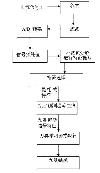
[0022] The tool wear state monitoring method of the present invention realizes the monitoring of the tool wear VB by acquiring the current signal of the machine tool drive motor, a series of signal processing and feature extraction selection processes, and finally through the tool wear monitoring process.

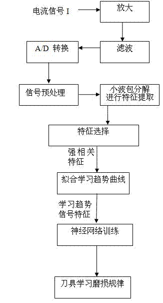
[0023] First, establish the tool learning wear law in the learning library through the following steps:

[0024] (1) Use the Hall current sensor to measure the three-phase output current of the drive motor of the CNC machine tool respectively;

[0025] (2) The measured output current is respectively amplified, filtered and A / D converted to obtain a current digital signal, which is the processing signal;

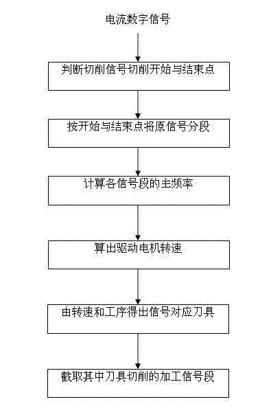
[0026] (3) Preprocessing the processing signal to obtain the current signal segment when the learning tool is cutting;

[0027] The processing signals obtained throug...


PUM


Abstract

The invention belongs to the field of numerical control machine tool wear measurement, and discloses a numerical control machine tool wear monitoring method. In the method, servo drive motor current signals of a numerical control machine can reflect the change of a cutting load along with the tool wear; the acquired servo drive current signals are analyzed; the signals are decomposed in a frequency domain by a wavelet packet decomposition technology, and time-frequency domain characteristics of the signals in each frequency domain range are obtained and a plurality of characteristics stronglycorrelated to the tool wear are automatically selected; the tool wear process is learned through a neural network and a tool wear rule is obtained; in reverse, the tool wear characteristics are obtained in real time and are matched with the tool wear rule obtained through learning so as to monitor the tool wear state. The method solves a problem that the conventional tool wear monitoring method cannot realize online real-time monitoring, the servo drive signals of the numerical control machine are utilized, the integration with a numerical control system is easy to realize, the monitoring cost is reduced and the monitoring accuracy is ensured.

Description

technical field [0001] The invention belongs to the field of tool wear measurement of numerical control machine tools, and relates to an online and real-time monitoring method for the tool wear state in mass production. Background technique [0002] Over the years, scholars at home and abroad have done a lot of work in the online monitoring of tool wear, and have achieved remarkable results in the fields of monitoring methods, monitoring parameter selection, and signal processing and identification. Some methods have been used in production. The traditional tool wear state monitoring method is based on the relevant characteristics of the tool volume loss, and directly obtains the tool wear value through contact measurement or CCD imaging. For example, see the Chinese patent application number: CN200910031737.9, and the title of the invention is: CNC milling tool wear measurement method based on shape replication, which copies the shape of the tool on the copy material to rea...

Claims


Application Information

Patent Timeline
Patent Type & Authority Patents(China)
IPC IPC(8): B23Q17/09
Inventor 李斌刘红奇毛新勇丁玉发彭芳瑜毛宽民
Owner HUAZHONG UNIV OF SCI & TECH
Why Eureka
Try Eureka